Reinforcing carbon fibers as sensors: The effect of temperature and humidity Forintos N., Czigány T.
This accepted author manuscript is copyrighted and published by Elsevier. It is posted
here by agreement between Elsevier and MTA. The definitive version of the text was
subsequently published in [Composites Part A (Applied Science and Manufacturing),
131, 2020, DOI: 10.1016/j.compositesa.2020.105819]. Available under license CC-
BY-NC-ND.
Reinforcing carbon fibers as sensors: the effect of temperature and humidity
Forintos N.1,2, Czigány T.1,2*
1Budapest University of Technology and Economics, Faculty of Mechanical Engineering, Department of Polymer Engineering, 1111 Budapest, Műegyetem
rkp. 3.
2MTA-BME Research Group for Composite Science and Technology, 1111 Budapest, Műegyetem rkp. 3.
*czigany@eik.bme.hu
ABSTRACT
We investigated how temperature and relative humidity affects the electrical resistance of reinforcing carbon fibers in polymer composites. We used hybrid composites in which a tight, carbon fiber roving was laminated inside glass fiber-reinforced epoxy specimens. The electrical resistance of the carbon fibers was monitored continuously while the temperature or relative humidity was varied. The specific resistance was calculated in order to compare the different effects acting on the resistance of the carbon fiber. We found a relationship between temperature or relative humidity and specific resistance.
As a result, carbon fibers can be used in different applications (for example in cure process monitoring). On the other hand, the effects should be compensated for when the resistance of the carbon fiber is measured in a health monitoring application (e.g. as an elongation sensor).
KEYWORDS
A. Carbon fibers A. Glass fibers A. Hybrid
A. Multifunctional composites
1. INTRODUCTION
Fiber-reinforced polymer composites are widely used in all areas of life, for example in the automotive and the energy industry or in sporting goods. The advantages of composites are low density, high modulus and strength, good resistance to chemicals and high temperature and good workability [1]. In recent years, hybrid composites have been extensively researched. Hybrid composites have two different reinforcing materials or matrices. The main reason is that these composites can combine the advantages of the components, for example, the high
into account as well. A leading industry is wind energy production: to improve energy generation, bigger turbines, therefore longer blades are needed. The blades have high loads (centripetal force, vibration, etc.), which limits blade size for a given material. The most common reinforcing material used to be glass fiber because of its low price and relatively good mechanical properties. A stiffer material with lower density, for example carbon fiber, enables larger structures, but to reduce cost, engineers combine glass and carbon reinforcing fibers [2].
Another advantage of hybrid composites is that they can be engineered to avoid catastrophic failure—instead, failure can be gradual (pseudo-ductility). In this kind of material, different failure methods can occur simultaneously:
fragmentation of the high-modulus, low-strain reinforcement (carbon fiber), delamination between the layers of different modulus/strain (glass and carbon fiber) layers and failure of the high-strain reinforcement (glass fiber) [3]. In application areas, where high impacts, for example collisions can be expected, non-catastrophic failure means operational and life safety.
Most polymer composite applications are structural, where the mechanical properties of the reinforcing fibers are exploited. Some important, and rapidly growing fields, such as industry 4.0 or autonomous and zero emission transportation require lighter, more compact products that can collect more data throughout their lifetime. These requirements can be met with multifunctional
definition created by Ferreira et. al. [5]: “a material is multifunctional when it has an additional function (e.g. electrical, biological, etc.) besides its structural property”. Carbon materials (fibers, nanotubes) have good electrical properties, which can be used for additional functions, such as resistive heating [6], electromagnetic shielding, energy storage or health monitoring [7].
A health monitoring sensor can be created if the resistance of the reinforcing carbon fiber is measured; it is called the electrical resistance change method (ERCM) [8]. Carbon fibers used as a built-in sensor have many advantages: this configuration does not need any external sensors, therefore it is easier to manufacture and more cost-efficient, it does not have the “size-effect”, which means that the fibers do not cause inhomogeneity, and carbon fiber can sense the state of the base material locally.
ERCM is widely used to monitor strain and failure in composites. Todoroki [9] made multifunctional carbon fiber-reinforced specimens, where the fibers are used for strain measurement. He measured the electrical resistance of the specimens during a tensile test and perceived similar behavior to that of conventional strain gages. The gage factor in his experiment was 2.6, which means the 1% of elongation would result in a 2.6% change in resistance.
Damage sensing is crucial in structural parts. With ERCM, it is possible to detect fiber or matrix failure, or delamination. Vavouliotis et al. [10] measured the
electrical resistance of carbon fiber-reinforced composites to predict failure during fatigue loading. They tested carbon fiber-reinforced epoxy specimens with a cyclic load. Based on their results, they found good correlation between physical changes in the composite structure and change in electrical resistance, therefore, their measuring arrangement made it possible to predict the fatigue life of the composite. In their experiment, they compensated for the effect of temperature: they measured the temperature, calculated the change in resistance based on the temperature change and corrected the measured resistance value with it. They used an experimental value for the linear temperature coefficient.
They compared the original and corrected resistance values and showed that there is no significant difference.
With the spread of ERCM, it is important to understand what else has an effect on resistance besides elongation and failure. The environment (pressure, temperature, humidity) of the self-sensing structure has an impact on the electrical resistance of carbon fibers. The effect of temperature on the resistance of carbon materials has been known for a long time, but it was considered a disadvantage of the material. Schulte and Baron [11] mentioned in their paper that the heat generated by fatigue causes a change in resistivity, which can lead to a misinterpretation of ERCM results. Heat can also be generated by the Joule
effect: as current flows in a resistor (voltage measurement, lightning strikes, etc.), atomic-scale collisions generate thermal energy in the material. This effect can be reduced by improving the conductivity of the material but should be taken into account [12]. In a recent research project, the researchers exploited the heat dependence of the resistance of carbon fiber: they used the interlaminar interface of two carbon fiber felts laid perpendicularly on each other as a sensor for temperature and thermal damage [13]. Takashi and Hahn [14] investigated the electrical resistance of a graphite fiber-reinforced polymer in different directions.
They measured a negative thermal coefficient of resistivity (which means a decreasing electrical resistance with increasing temperature) in the longitudinal, transverse and through-thickness directions.
Other environmental effects and relative humidity can also be determined by ERCM. Wang et al. [15] measured the contact resistance of an overlapping carbon fiber felt to estimate relative humidity. They explained this effect with the water uptake of the epoxy matrix, which causes the matrix to swell, thus increasing the distance between the carbon fiber layers.
The aim of this paper is to investigate the relationship between the temperature or relative humidity and the electrical resistance of reinforcing carbon fiber.
2. EXPERIMENTAL SETUP
In our experiment, we used continuous carbon fiber tow (Sigrafil C T24- 5.0/270-E100, SGL Carbon Group, Germany) for resistance measurement (Table 1). The carbon fiber products of SGL Carbon are used for automotive composite parts manufactured in Germany.
Properties Units Sigrafil C T24-5.0/270-E100
Number of filaments 24000
Fineness of yarn dry tex (g/1000m) 1600
Density g/cm3 1.79
Filament diameter µm 6.9
Tensile strength GPa 5
Tensile modulus GPa 270
Elongation at break % 1.9
Single filament resistivity µΩm 14
Table 1. Material data of the Sigrafil C T24-5.0/270-E100 carbon fiber [16]
The carbon fiber yarn was laminated in a glass fiber-reinforced composite to insulate it from the environment electrically. The composite consists of two layers of glass fiber fabric RT 300 (SG Vetrotex Renforcement S.A., France) under
and above the carbon fiber and the reinforcement was impregnated with the epoxy matrix (MR 3016 epoxy with MH 3124 hardener, 100:40 mixing ration, Ipox Chemicals Kft., Hungary). During hand lamination, the carbon fibers were fastened by bolts at both ends of the laminate. The specimens were cured in an oven (Despatch LBB2-27-1CE, Despatch Industries, USA) at 90 °C for 8 hours.
After cutting the specimens (250x40x3 mm), we made electric contact by winding wires around the carbon fibers. We chose four-wire resistance measurement, therefore two wires were fitted at each end of the fibers. In this arrangement, the electric current flowed from A to D and the voltage was measured between B and C (Figure 1.) with an Agilent 34970A data logger (Agilent Technologies, USA).
Figure 1 Layout of the experiment. Applying current through contacts “A” and “D”, and measuring voltage between contacts “B” and “C”.
The heat dependence tests were carried out in the heat chamber of a Zwick Z250 multifunctional material tester (Zwick, Germany). The chamber is heated electrically and cooled by liquid nitrogen. The temperature and the heating rate are controlled and monitored through the Zwick TestXpert program. All the specimens were measured in a heat cycle, which started with cooling to −20 °C to set the starting temperature, followed by heating up to 120 °C at a heating rate of 10 °C/min and then cooling back to −20 °C at cooling rate of −5 °C/min. We examined the temperature–resistance relationship between 0 °C and 100 °C to avoid the inaccuracy of the temperature held at the two extreme values. We measured the temperature with a K type thermocouple and an Almemo 8990-6 data acquisition module (Ahlborn Meß- und Regelungstechnik GmbH, Germany), which was calibrated with the temperature of boiling water and melting ice cubes.
Based on our results, we created two experiments for demonstration purposes. The first was a curing monitoring experiment, where we measured the temperature of a crosslinking epoxy resin (250g, 270x170x17 mm) with a thermal camera (FLIR A325 SC, FLIR, USA). We evaluated the temperature profile by averaging the pixels corresponding to the carbon fibers. In the second experiment, we performed a tensile test in a Zwick Z250 multifunctional material tester (Zwick, Germany) at a tensile speed of 2mm/min. Elongation was
measured by the crosshead travel monitor. In both experiments, the resistance of a tight carbon fiber bundle was measured by the four-point method.
The relative humidity (RH) dependence tests were carried out in an HCP153 humidification chamber (Memmert, Germany). RH was changed continuously from the lowest possible value to 95% at a given temperature with the use of evaporating water. We repeated the experiment at different temperatures (30 °C, 40 °C, 50 °C and 60 °C) as RH depends on temperature. The temperature and humidity data were collected with the sensors of the chamber.
3. RESULTS AND DISCUSSION
3.1. Heat dependence
Figure 2 shows a typical measured resistance curve as a function of time during heat dependence measurement.
Figure 2 Resistance as a function of temperature during a heating-cooling cycle for heat dependence measurement
During evaluation, we examined the heating and cooling phases separately, both between 0 °C and 100 °C. This range is the same as during the calibration of a metallic thermometer. To compare different specimens with different initial resistance, we calculated specific resistance 𝑅𝑠 by Equation (1):
𝑅𝑠 = 𝑅𝑡𝑅−𝑅0
0 ∙ 100, (1)
where the 𝑅0 reference point was the measured resistance value at 0 °C and 𝑅𝑡 was the measured resistance value at temperature 𝑡. Figure 3 shows the specific resistance as a function of temperature; the heating and cooling phases are shown separately.
a b
Figure 3. Specific resistance as a function of temperature during heating (a) and cooling (b)
Based on the results, the temperature-specific resistance diagram can be approximated with a straight line. The approximation is similar to the first order Equation (2) of the temperature dependence of metal resistance thermometers:
𝑅𝑡 = 𝑅0∙ (1 + 𝛼 ∙ 𝑇) (2)
in another form is Equation (3):
𝑅𝑡−𝑅0
𝑅0 ∗ 100 = 𝛼 ∙ 𝑇, (3)
where 𝛼 is the linear temperature coefficient. 𝛼 is the steepness of the linear trend line fitted by the least squares method. In our heating experiment, the calculated coefficient is 𝛼ℎ𝑒𝑎𝑡 = −0.02387 ± 0.00279 [°𝐶%], and the value during cooling is 𝛼𝑐𝑜𝑜𝑙 = −0.02409 ± 0.00325 [%°𝐶].
0.5
-0.5
-1.5
-2.5 0.5
-0.5
-1.5
-2.5
In our experiments, the values of 𝛼 were negative, which means that the carbon fiber has a negative temperature coefficient (NTC). The values are almost the same during heating and cooling and are close to the values published earlier [14, 17]. These results have two implications. On the one hand, carbon fiber can be used as a temperature sensor in various applications. For example, the crosslinking of a thermosetting matrix generates heat, which is a good indicator of the degree of cure. For demonstrating purposes, we created an experiment where the epoxy described before was cured in a container (Figure 4). During the crosslinking process, the resistance of the impregnated carbon fiber roving was monitored as described before.
Figure 4 Temperature and specific resistance during the crosslinking of epoxy. While carbon fibers measure volume temperature distribution, the thermal camera measures surface
temperature distribution.
The temperature values from the thermo camera show a rapid increase in temperature during the chemical reaction of crosslinking. After the maximum temperature was reached, the specimen slowly cooled down in air. As expected, resistance dropped rapidly while the temperature increased. After the experiment, we calculated the temperature from the specific resistance based on equation (3) and the measured linear temperature coefficient (4). The temperature measured by the thermal camera differs from the temperature calculated from the resistance of carbon fibers. This could be caused by the measurement layout: the thermal camera measures the heat at the top surface of the epoxy (surface temperature distribution), while the carbon fibers are embedded in the epoxy resin, where volume temperature distribution is measured. In a real-life application, for example in a wind turbine blade factory, this calibration curve could be precisely measured when technological parameters are determined, and the other curves, measured during mass production, can be compared to the original calibration. With this, a quality control system can be created, where the resistance measurement of carbon fibers could ensure that the part received the necessary heat treatment. With these results, a curing process control system can also be created, where feedback is based on the reinforcing carbon fiber.
A change in resistance caused by a change in temperature, on the other
performed a tensile test (Z250 tensile tester, Zwick, Germany) on the specimens prepared for this test. We measured elongation (from crosshead travel) and resistance (Figure 5).
Figure 5 Specific resistance as a function of elongation during the tensile test
The gauge factor (GF) at the starting, linear period (until around 1% elongation), which is the relationship between elongation and specific resistance, was 𝐺𝐹 = 0.7117 [−] in our experiment. The change in resistance just before breaking is the same as a change a 60 °C temperature decrease would cause. This means that the effect of temperature should be compensated for either during measurement (e.g.
with a Wheatstone bridge) or during evaluation: the measured change in resistance should be corrected based on the linear temperature coefficient and external temperature.
3.2. Relative humidity dependence
In our RH experiment, specific resistance was calculated based on the initial resistance at the beginning of the test according to Equation (4):
𝑅𝑅𝐻−𝑅𝑖𝑛
𝑅20 , (4)
where 𝑅𝑖𝑛 is the initial resistance of the sample and 𝑅𝑅𝐻 is the resistance at 𝑅𝐻%
relative humidity. Figure 6 shows the measured specific resistance as a function of RH at different temperatures.
Figure 6 Specific resistance as a function of relative humidity at different temperatures
A linear line was fitted on the measured data for each temperature. The Equation (5) of this line is similar to the Equation (3) that describes heat dependence.
𝑅𝑅𝐻−𝑅20
𝑅20 ∗ 100 = 𝛽 ∙ 𝑅𝐻%, (5)
0.0 -0.1 -0.2 -0.3 -0.4 -0.5
where 𝛽 is the linear humidity coefficient. 𝛽 shows how much the resistance changes in a 1 Ω section of carbon fiber as a result of 1% change in RH. The calculated average coefficient is 𝛽 = −0.0056 ± 0.00044 [−].
𝛽 and the effect of relative humidity on resistance is one order of magnitude smaller than the effect of temperature, but it should be compensated for when carbon fibers and their electrical properties are used.
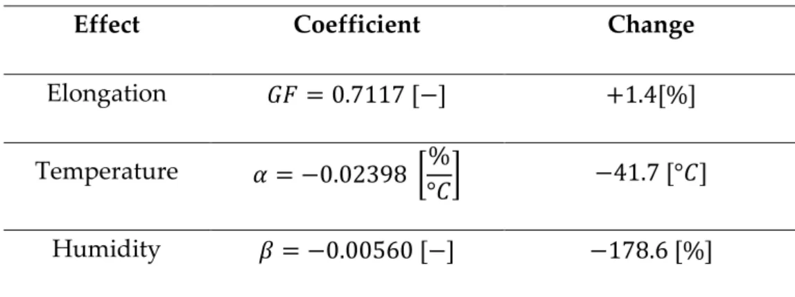
Table 2. summarizes the coefficients of external impacts, such as elongation, temperature and humidity.
Effect Coefficient Change
Elongation 𝐺𝐹 = 0.7117 [−] +1.4[%]
Temperature 𝛼 = −0.02398 [%
°𝐶] −41.7 [°𝐶]
Humidity 𝛽 = −0.00560 [−] −178.6 [%]
Table 2. Coefficients of different effects. Gf – gauge factor; α – linear temperature coefficient;
β – linear humidity coefficient. “Change” means the required change in the effect to change the resistance of the carbon fiber by 1%
The results show that ERCM of carbon fibers are most sensitive to elongation, but temperature also has a high effect on resistance. The effect of humidity is not that significant. In a real-world situation, all the different impacts could influence the resistance and they should be taken into account when ERCM
4. CONCLUSION
Carbon fibers are widely used as sensors where their electrical properties are exploited with an electrical resistance change method. In literature examples only one effect is monitored, but in a real-life situation multiple influences simultaneously effect the resistance of the carbon fibers and they can cancel each other out.
We monitored the resistance of a laminated carbon fiber yarn during a heating-cooling cycle and also at different relative humidities (RH). The measured values show a clear relationship between a change in resistance and a change in the environment (temperature or RH). Both functions are similar to the equation of metallic thermometers and based on that, we introduced two coefficients. We named them linear temperature coefficient and linear humidity coefficient. Elongation, temperature and humidity have a different effect on resistance. Our results show that elongation has an order of magnitude larger impact than temperature and two orders of magnitude larger than humidity.
All of our experiments were continuous tests, where only the change in temperature and change in humidity were monitored. Static tests could result in other relationships between electrical resistance and environmental properties,
as the specimen would saturate with moisture, which would result in a nonlinear relationship between resistance and temperature.
As a result, carbon fibers can be used as temperature or humidity sensors in multifunctional composites, especially detecting changes in these parameters.
However, multiple factors act on the resistance of carbon fibers at the same time, and these should be taken into account: for instance, temperature, humidity, mechanical load or pressure. These effects should be separated or compensated during electrical resistance measurement.
ACKNOWLEDGEMENTS
This work was supported by the OTKA (K 116070 and K 120592) and NVKP (NVKP_16-1-2016-0046) projects of the National Research, Development and Innovation Office (NKFIH), by the Higher Education Excellence Program of the Ministry of Human Capacities in the frame of the Nanotechnology research area of the Budapest University of Technology and Economics (BME FIKP-NANO), and the National Research, Development and Innovation Fund (TUDFO/51757/2019-ITM, Thematic Excellence Program). We would like to thank Viktor Jurasek for his measurements.
REFERENCES
[1] Geier N, Szalay T, Takács M. Analysis of thrust force and characteristics of uncut fibres at non-conventional oriented drilling of unidirectional carbon fibre-reinforced plastic ( UD-CFRP ) composite laminates. Int J Adv Manuf Technol 2019;100:3139–3154. doi:10.1007/s00170-018-2895-8.
[2] Mishnaevsky L, Id J, Branner K, Petersen HN, Beauson J, Mcgugan M, et al. Materials for Wind Turbine Blades : An Overview 2017:1–24.
doi:10.3390/ma10111285.
[3] Fotouhi M, Jalalvand M, Wisnom MR. Notch insensitive orientation- dispersed pseudo-ductile thin-ply carbon / glass hybrid laminates.
Compos Part A 2018;110:29–44. doi:10.1016/j.compositesa.2018.04.012.
[4] Forintos N, Czigany T. Multifunctional application of carbon fiber reinforced polymer composites: Electrical properties of the reinforcing carbon fibers – A short review. Compos Part B Eng 2019;162:331–43.
doi:10.1016/j.compositesb.2018.10.098.
[5] Ferreira ADBL, Nóvoa PRO, Marques AT. Multifunctional material systems: A state-of-the-art review. Compos Struct 2016;151:3–35.
doi:10.1016/j.compstruct.2016.01.028.
[6] Wang FX, Liang WY, Wang ZQ, Yang B, He L, Zhang K. Preparation and property investigation of multi-walled carbon nanotube ( MWCNT )/
epoxy composite films as high-performance electric heating ( resistive heating ) element. Express Polym Lett 2018;12:285–95.
doi:10.3144/expresspolymlett.2018.26.
[7] Chung DDL. Electrical applications of carbon materials. J Mater Sci 2004;39:2645–61. doi:10.1023/B:JMSC.0000021439.18202.ea.
[8] Naghashpour A, Van Hoa S. A technique for real-time detecting, locating, and quantifying damage in large polymer composite structures made of carbon fibers and carbon nanotube networks. Struct Heal Monit 2015;14:35–45. doi:10.1177/1475921714546063.
[9] Todoroki A. Electric resistance change method for cure/strain/damage monitoring of CFRP laminates. Key Eng Mater 2004;270–273:1812–20.
doi:10.4028/www.scientific.net/KEM.270-273.1812.
[10] Vavouliotis A, Paipetis A, Kostopoulos V. On the fatigue life prediction of CFRP laminates using the Electrical Resistance Change method. Compos Sci Technol 2011;71:630–42. doi:10.1016/j.compscitech.2011.01.003.
[11] Schulte K, Baron C. Load and failure analyses of CFRP laminates by means of electrical resistivity measurements. Compos Sci Technol 1989;36:63–76.
doi:10.1016/0266-3538(89)90016-X.
[12] Kumar V, Yokozeki T, Okada T, Hirano Y, Goto T, Takahashi T, et al. Effect of through-thickness electrical conductivity of CFRPs on lightning strike damages. Compos Part A Appl Sci Manuf 2018;114:429–38.
doi:10.1016/j.compositesa.2018.09.007.
[13] Chung DDL. Carbon materials for structural self-sensing, electromagnetic shielding and thermal interfacing. Carbon N Y 2012;50:3342–53.
doi:10.1016/j.carbon.2012.01.031.
[14] Takahashi K, Hahn HT. Investigation of temperature dependency of electrical resistance changes for structural management of graphite/polymer composite. J Compos Mater 2011;45:2603–11.
doi:10.1177/0021998311416683.
and stress on the interlaminar interface of carbon fiber polymer-matrix composites, studied by contact electrical resistivity measurement. J Adhes 2002;78:189–200.
[16] SGL Sigrafil carbon tow catalog n.d. www.sglgroup.com (accessed December 10, 2018).
[17] Crasto AS, Kim RY. Using carbon fiber piezoresistivity to measure residual stresses in composites. Am. Soc. Compos. Eight Proc., CRC Press; 1993.