Script-aided generation of Mental Cutting Test exercises
using Blender
Róbert Tóth
University of Debrecen, Faculty of Informatics toth.robert@inf.unideb.hu
Submitted: November 15, 2020 Accepted: March 12, 2021 Published online: March 29, 2021
Abstract
This paper presents a possible generation process how to efficiently model, export and render resources ofMental Cutting Testexercises with the use of Blender.
Keywords:spatial skills, Mental Cutting Test, Blender
1. Introduction
The spatial availability of people can be measured by using different types of tests such asMental Cutting TestandMental Rotation Test. Offering exercises ofMental Cutting Test (MCT) is a widely used method in which people have to determine the shape of the intersection of a 3D shape and a plane. The test was introduced in the USA in the late 1930s [4], while researches still deal with this topic nowadays [12]. Virtual Reality (VR)has become a widely supported and popular method to extend our reality. During the last decade, researchers started developing VR aided applications to extend the functionality of classic MCT exercises [7]. On the other hand, the use of VR requires head gears which results in strong limitations on the researches. In the meantime,Augmented Reality (AR) has also become a popular way to extend our reality and interact with the users in a more efficient way without any investments – we only need to use the camera of our mobile devices to place objects onto any surfaces. While this paper focuses on the technical description doi: https://doi.org/10.33039/ami.2021.03.011
url: https://ami.uni-eszterhazy.hu
147
of a recently designed, efficient procedure to generate MCT exercises, we have to mention that many Hungarian and East European researchers deal with various approaches of developing spatial skills [1, 10, 11, 14, 15]. Thus, the proposed procedure has the opportunity to enhance the methods of a popular and actively researched topic both in national and international scientific context.
In 2019 the development of a new mobile application has started at the Faculty of Informatics, University of Debrecen with the aim of improving the spatial skills of its users by offering MCT exercises [16]. The exercises are derived from the classic MCT, but Augmented Reality and the principle of gamification [8] are also being used to support, engage and motivate the users.
1.1. Terminology
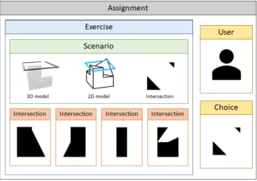
Another important key of a practicing application is the number of different ex- ercises. To efficiently construct the dataset, three abstraction levels have been introduced (see Figure 1).
1. Scenarios: A scenario consists of the basic resources that are needed to rep- resent an exercise: the isometric projection of a 3D shape that is intersected by a 2D plane (so called 2D model), and the shape of their intersection (so called answer or shape of intersection). To support the users with the AR function, a new component has been introduced (so called3D model) which is a 3D object both containing the 3D shape and a 3D frame that describes the intersection plane (so calledintersection).
2. Exercise: Classic MCT exercises contain four additional shapes as wrong aswers. Thus, we must construct alternative answers to form a real exercise.
In our terminology, an exercise is a composition of a scenario and answers of another scenarios. Thus, multiple exercises can be constructed of a sce- nario by permutating the wrong answers. The method of choosing the wrong answers can depend on several factors: to form a practice exercise for begin- ner users, we should minimize the similarity between the alternatives; on the other hand, MCT exercises that are used to measure skills usually contain very similar alternatives.
3. Assignment: An assignment is an instance of an exercise that is assigned to a user. Each assignment is generated from the exercises that are defined by the instructor – thus, the users’ choices and spatial skills can be easily compared by processing the assignments.
Files that are rendered or exported from Blender [5] and used to display or post- process assignments (2D models, 3D models and intersections) are calledresources.
1.2. Resources
As we described in Section 1.1, to form a scenario three resources are required:
Figure 1. Entities and resources that form an assignment.
1. A 2D image that contains the 3D shape and the 2D plane applying the special isometric projection of MCT exercises.
2. A 3D model that contains the 3D shape and the 2D plane and can be in- stanced and displayed with the AR function.
3. A 2D image that contains the shape of the intersection of the 3D shape and the intersection plane. This resource is the solution of the classic MCT exercises.
Several file formats can be selected for these resources. Two requirements have been constructed towards the file formats:
1. Image format should be scalable.
2. The size of the resources must be minimized .
To fulfil the requirements, SVG [3] was chosen for image resources, while GLB [9]) was chosen for 3D models. On the other hand, a rastergraphic input format is also needed for post-processing methods. For that purpose, PNG [2] files are used.
GLB models can be exported and PNG images can be rendered in Blender without any add-ons, while FreeStyle and its FreeStyle SVG Exporter are used to render SVG files.
1.3. Scenarios
As the focus is on the generation of assignments, further sections will describe this process. The aim is to give a well detailed description of the methods that are used
to prepare, render and postprocess all the resources that are needed to construct a scenario. During this research, Blender is used to design our models, then generate the required output files in SVG and GLB formats as well as additional PNG images are also being generated to support the image processing that is used to determine similarity between the shapes of intersection. Blender provides various methods to design and manipulate models while it also offers a well-detailed API in Python language [6]. Thus, a library has been designed and implemented that supports the instructor through the steps of the scenario development. As a result, multiple scenarios can be generated starting from a single 3D shape by applying rotation vectors and predefined intersection planes. However, the steps still need some human contribution and configuration that can be given in JSON markup language.
1.4. The process
Based on the API of Blender an iterative workflow of development was designed to generate the required resources from the modeller software. The algorithm contains the following steps:
1. Prepare scenarios.
(a) Design 3D shapes.
(b) Design intersection planes.
(c) Rotate shapes.
2. Render and export resources.
(a) Render 2D models.
(b) Export 3D models.
(c) Create and render the shapes and intersections.
3. Post-process scenarios.
(a) Filter scenarios.
(b) Substitute answers.
(c) Rotate and scale answers.
(d) Edit, compress and style SVG resources.
2. Preparation
2.1. Design 3D shapes
MCT exercises consist of various models, but two basic approaches can be used to design them:
1. Start with a basic shape, then transform its vertices, edges and faces (mostly with subdivision and extradition).
2. Start with multiple basic shapes, then construct compositions of them by calculating their unions, intersections or differences. This method can be supported by Blender’s boolean modifier. However, the limitations of this operation will be described in Section 3.3.
We have to keep in mind that only the 2D projection of the model is displayed in classic MCT exercises to the users and they can only examine three faces of the shape without limitations. Thus, most of the details should be concentrated into these sides – otherwise people will not be able to determine the shape of all the intersections.
All shapes that are scaled to have a maximum size of 2 in each dimensions.
Thus, the size of shapes are uniformed and they fill the viewport of the camera that is being used to render 2D models.
2.2. Design intersection planes
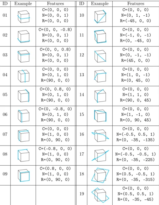
Due to the previously mentioned limitations of the applied projection, most of the MCT exercises only use a few intersection planes. However, our goal is to offer various scenarios. Thus, one pillar of the permutation is the various usage of inter- section planes. Table 1 shows the 19 planes can be used in the generation process, mostly resulting a non-empty intersection. Each intersection plane is described with vectors𝐶, 𝑁 and 𝑅 (𝐶, 𝑁, 𝑅 ∈ ℛ3), where 𝐶 contains the coordinates of a point that is on the plane, 𝑁 is the normal of the intersection plane, while𝑅 is a rotation vector and will be used in the further transformations.
Consider a cube with dimensions(2, 2, 2)which geometry origin is in loca- tion (0, 0, 0). Intersections 0-9 are parallel with one of the faces of the shape, intersections 10-15 contain the diagonals of the faces, while intersections 16-19 contain the diagonals of the shape.
2.3. Rotate shapes
Scenarios can be permuted easily by applying rotation on the shapes around their origins while intersection planes are still the same. This method has two advan- tages:
1. Firstly, multiple scenarios containing the same shape and intersection plane can be constructed whose intersection is still the same. As a result, users can practice on the same scenarios using different perspectives.
2. Secondly, the shape of the intersection also depends on the features of the 3D shape. Thus, different types of intersections can be generated by just simply rotating the object and still using the same intersection planes.
Table 1. Intersection planes with their𝐶,𝑁and𝑅vectors demon- strated with the cube.
ID Example Features ID Example Features
01 C=(0, 0, 0)
N=(0, 0, 1) R=(0, 0, 0)
10 C=(0, 0, 0)
N=(0, 1, -1) R=(-45, 0, 0)
02 C=(0, 0, -0.8)
N=(0, 0, 1)
R=(0, 0, 0) 11 C=(0, 0, 0)
N=(-1, 0, -1) R=(0, -45, 0)
03 C=(0, 0, 0.8)
N=(0, 0, 1) R=(0, 0, 0)
12 C=(0, 0, 0)
N=(0, -1, -1) R=(45, 0, 0)
04 C=(0, 0, 0)
N=(0, 1, 0)
R=(90, 0, 0) 13 C=(0, 0, 0)
N=(1, 0, -1) R=(0, 45, 0)
05 C=(0, 0.8, 0)
N=(0, 1, 0) R=(90, 0, 0)
14 C=(0, 0, 0)
N=(1, 1, 0) R=(90, 0, 45)
06 C=(0, -0.8, 0)
N=(0, 1, 0)
R=(90, 0, 0) 15 C=(0, 0, 0)
N=(1, -1, 0) R=(0, 90, 45)
07 C=(0, 0, 0)
N=(1, 0, 0) R=(0, 90, 0)
16 C=(0, 0, 0)
N=(-0.5, 0.5, 1) R=(0, -35, -135)
08 C=(-0.8, 0, 0)
N=(1, 0, 0)
R=(0, 90, 0) 17 C=(0, 0, 0)
N=(-0.5, -0.5, 1) R=(0, -35, -225)
09 C=(0.8, 0, 0)
N=(1, 0, 0)
R=(0, 90, 0) 18 C=(0, 0, 0)
N=(0.5, -0.5, 1) R=(0, -35, -315)
19 C=(0, 0, 0)
N=(0.5, 0.5, 1) R=(0, -35, -45)
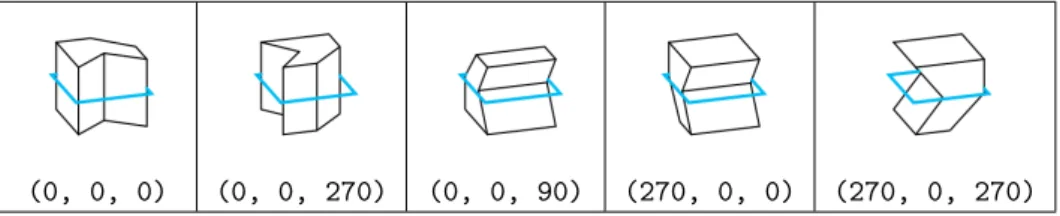
The number of possible rotations – consequently the number of different permu- tations – depends on the features of the shape. Table 2 shows the five orientations that can be used in most of the cases.
Table 2. A shape with its intersection plane, rotated by different 𝑅vectors.
(0, 0, 0) (0, 0, 270) (0, 0, 90) (270, 0, 0) (270, 0, 270)
3. Generate resources
3.1. 2D model
The camera that is used to render 2D models is created withortographic projection at location (3.3, -1.25, 1.4), rotation (68.5, 0, 72), scale (1.0, 0.772, 1.0) andortographic scale 4.50. These properties result the same isometric per- spective as the classic MCT exercises. The algorithm of the rendering contains the following steps:
1. The shape is moved into location (0, 0, 0)(see Figure 3).
2. The frame which represents the intersection plane is displayed. All 19 frames are pre-modelled and subdivided into200*200subfaces in its local𝑋 and𝑌 dimensions. Also, the outer edges of the frame are marked asFreeStyle edges.
3. The SVG resource is being rendered with FreeStyle by selecting all thecontour and FreeStyle edges. The output will be modified and styled in the post- processing steps.
3.2. 3D model
Secondly, the 3D model is being exported in GLB format. Thus, a white material is applied to the shapes, while one of the 19 thick black frames is also added to represent the intersection planes. The model is exported with Blender’s export function.
3.3. Intersection
Thirdly, the most complex step of the rendering process is to create and render the shape of the intersection.
In the first phase of the research, sample scenarios have been designed by using theboolean modifier with itsintersectionoption [17]. However, several issues could be found. As the operator deals with non-zero volume meshes, the intersection planes were created with constant, non-zero heights (values were chosen from range [0.001,0.02]). To render the shape of intersection, a camera was added to location
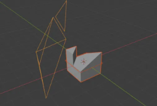
Figure 2. The shape with its frame rep- resenting the intersection plane with the camera that is used to render 2D models.
Figure 3. A thick black frame is being exported with the 3D model.
(0, 0, 3.2)with rotation(0, 0, 90)and the shapes were moved to location(0, 0, 0). Contour edges were marked asFreeStyle edges and the scene was rendered with FreeStyle. Unfortunately, the operator regularly miscalculated the edges of the shapes by adding extra edges and vertices the shape. As the documentation points out, only manifold meshes are guaranteed to give proper results, as well as we should also avoid any co-planar faces or co-linear edges of shapes. The first criterion can be avoided in most of the scenarios, but the second criterion cannot be satisfied since most of the MCT scenarios contain co-linear edges. Thus, we could not use this modifier anymore because extra vertices and edges were added in various cases which were not detectable with a deterministic algorithm.
After that, the usage of Blender’sbisection operator started. This operator is accessible from the user interface, while it is also supported by the Python API.
The algorithm is the following:
1. Create an independent duplicate of the 3D shape, then clear its FreeStyle edges.
2. Bisect the shape by applying the bisect()function. The plane is described by coordinate 𝐶, and normal 𝑁 of the selected intersection, described in Table 1.
3. The edges of the object that are in the intersection plane are automatically selected by thebisect function. Flip the selection and delete all the unse- lected vertices and edges to eliminate all the features except the intersection.
Mark the border edges of the intersection asFreestyle edges.
4. Apply a global rotation on the shape that is described by vector 𝑅 of the intersection plane to flatten it. Now the 𝑍 coordinates of all vertices and edges are 0. Calculate the geometry origin, and move the intersection to location(0, 0, 0).
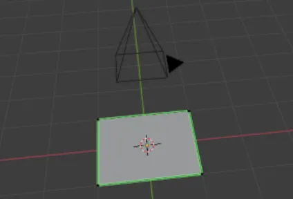
5. Determine the dimensions of the intersection and scale the object to fill the viewport of the camera with the maximum size of (2, 2, 0).
6. Render the SVG and PNG resources that contain the shape of the intersec- tion. The SVG file is being used as the output resource, while the PNG format supports the post-processing.
Figure 4. The shape of the answer under the camera being used to render the resource files.
4. Post-processing
The steps of the modelling process and the resource files that are needed to con- struct a scenario have already been presented. In this section the post-processing steps that are used to improve the quality of our resources as well as can be used to modify the configuration file of the scenario will be described.
4.1. Filter scenarios
As all the required combinations of shapes, rotations and intersection planes have been generated, at this point the generated resources must be examined. Differ- ent combinations of objects, rotations and intersection planes can result unusable scenarios. Consider the following cases:
1. The intersection plane and the 3D shape do not have an intersection. Thus, the intersections are empty.
2. An important detail of the shape is hidden from the actual perspective, thus users cannot give deterministic answer.
3. Two or more rotations result the same scenario because of the symmetry of the object.
In all cases, the scenario should be omitted from the database and be skipped in the further executions of rendering. Case (1) and (3) could be determined auto- matically by processing the PNG formats of intersections and 2D models. However,
case (2) should be detected by the instructor. In the current implementation, case (1) is detected automatically. Our configuration file will store all the combinations that should not be applied anymore.
4.2. Substitute answers
Of course, two or more scenarios can result the same shape of intersection. Further- more, in many cases they only differ from each other in their rotation. Thus, all the similarities must be discovered and the same shapes must be substituted with only one, uniformed instance. Thus, a simple image processing algorithm was developed which reads and compares the PNG resources of intersections by determining the ratio of their common pixels. This algorithm can easily discover that intersections are the same except their rotation by rotating them around the Z axis with 90, 180 and 270 degrees. On the other hand, we can flip the images both vertically and horizontally to transform them into the same state. Similarities that are de- tected by this algorithm are added to the configuration file. Of course, there are several cases in which this solution cannot determine the similarity (e.g. one shape is rotated with 45 degrees). Thus, feature detection and pairing algorithms were applied to the resources such as OpenCV’s SIFT and ORB [13]. Unfortunately, intersections are very simple shapes that do not have enough features. Thus, these algorithms cannot determine similarities with acceptable precision, the instructor must detect and configure these similarities manually.
4.3. Rotate and scale answers
As all the different shapes of intersections have been selected and the mapping has been defined between them, the selected shapes must be uniformed. The instructor can extend the configuration by describing a rotation that should be performed on the shape of intersection using axis Z. Then, all the intersections will be rotated and automatically scaled to the uniform size during further executions of the rendering script.
4.4. Edit, compress and style SVG resources
The SVG format which is being generated by the FreeStyle SVG plugin can be transformed into a more optimized format. The plugin generates unnecessary at- tributes (e. g. attributes of the Inkscape namespace), inline style attributes and adds unnecessary points on the edges of the shapes. Thus, the intersections are being manipulated using the Python minidom package to transform our vector graphics into a more compressed format without any loss of important data. Based on the features of SVG files, we can easily compress sizes by applying the following steps:
1. Dissolve all the points of paths if their neighbors are on the same line.
2. Merge or bisect g elements to better organize the path elements and make them able to apply CSS rules easier.
3. Replace the inline style attributes with CSS rules.
4. Remove redundant or unnecessary white spaces and commas from the docu- ment (e. g. from the attribute values ofpathelements and the indentation).
Unfortunately, several processors are not able to correctly cascade CSS rules to elements even though the recommendation supports this feature. As the An- droid packagePixplicitly’s Sharp being used during this research does not support cascading, we must skip step (3).
Table 3. An intersection in its original (a), transformed (b) and filled (c) state.
a b c
Table 4. A 2D scenario (a), its intersection (b) with rendering all of the edges, and its intersection (c) with rendering only border edges. The post-processing algorithm joins the separated paths (d)
and the shapes are being filled (e).
a b c d e
On the other hand,pathelements should be modified in this step. Of course, some of the operations (e.g. to fill thepathelements) could be done by theFreeStyle plugin in most of the cases, but an independent method is preferred to in-built so- lutions of Blender and several glitches can be caused byFreeStyle. Table 4 shows a scenario in which a hole is cut into a cube, which contains a prism. The bisect function subdivides the intersection, which results non-border edges. They can be skipped easily by marking only the border edges as FreeStyle edges. The SVG should contain three shapes: a square with a nested circle and another square. Un- fortunately,FreeStyle constructs three paths instead of one, representing correctly the outer square.
Thus, the non-looped edges are collected by the post-processing algorithm and joined into a loop which correctly form a shape. Then, the paths of intersections are
filled with black or white color alternately, depending on whether a path forms an outer shape or contained in a black or white shape. Thus, holes in the intersections are handled by the algorithm.
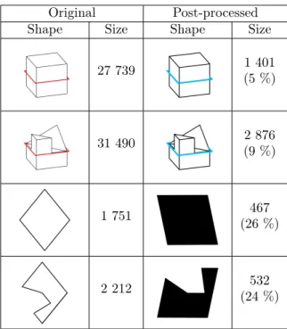
Table 5. Original and post-processed SVG resources with their sizes in bytes, compressed with𝜀= 0.2.
Original Post-processed
Shape Size Shape Size
27 739 1 401
(5 %)
31 490 2 876
(9 %)
1 751 467
(26 %)
2 212 532
(24 %)
5. Configuration file
As all the important steps of the generation algorithm have already been described, the schema of the configuration file can be introduced. The goal was to design a lightweight document that can contain all the needed metadata that should be used in any step of the generation process (see Figure 5):
1. rotations: The array of rotation vectors that can be applied to the 3D shape during the rendering.
2. skip: The array of scenario IDs (containing the ID of intersection plane and rotation). These combinations should be skipped due to any issue, e.g. empty intersection, or invisible details of the 3D shape.
3. compress-ratio: The value of𝜀that is used during the elimination of inner points of edges.
4. similarity-ratio: The value of𝜀that is used during the detection of similar answers.
5. answers: The list of objects that describes intersections selected as uniformed answers. Each instance is described by its scenario ID, rotation and the assigned id.
6. substitutes: The mapping between the original and the uniformed, replace- ment intersections.
{
"rotations": [
[0, 0, 0], [0, 0, 270], [0, 0, 90], [270, 0, 0], [270, 0, 270]
],
"skip": ["17.300", "17.303"],
"compression-ratio": 0.2,
"similarity-ratio": 0.9,
"answers": [
{ "scenario": "01.000", "rotation": 35, "id": "01"}, { "scenario": "01.100", "rotation": -90, "id": "02"}
...
],
"substitutes": {
"01.000": "01",
"01.003": "01",
"01.100": "02",
"01.300": "02"
...
} }
Figure 5. A sample configuration.
Configuration files can be manually edited as well as the values of properties skip,answersand substitutionscan be automatically created or modified. As a result, configurations can be iterated during multiple executions of the process.
Thus, further executions can be executed without any manual contributions. The interpretation of the configuration of Figure 5:
1. Permute scenarios with five rotations, skipping the combination of intersec- tion plane with rotation(270, 0, 0), then intersection plane 17 with rota- tion(270, 0, 270).
2. Use𝜀= 0.2in the compression of SVGs, and 0.9 to discover similar intersec- tions.
3. Rotate intersection of scenario 01.000with 35 degrees as uniformed answer 01, intersection of scenario01.100with -90 degrees as uniformed answer02.
4. Map the answers of scenarios 01.000 and 01.003 to uniformed answer 01, and answers of scenarios01.100and01.300to uniformed answer02.
6. Conclusion
This paper presented a script-aided process that was designed to support the design and rendering process of MCT exercises with the use of Blender and its Python API. With the combination of different intersection planes and rotations, almost 100 scenarios can be generated from a single model in most of the cases. The large number of scenarios lets us offer practicing exercises to improve the spatial skills of people. The shapes of intersections are being generated correctly in most cases; only the combination of overlapping intersection planes and faces can lead to non-deterministic results.
Acknowledgements. This work was supported by the construction EFOP-3.6.3- VEKOP-16-2017-00002. The project was supported by the European Union, co- financed by the European Social Fund.
References
[1] L. Baranová,I. Katreničová:Role of Descriptive geometry course in development of students’ spatial visualization skills, in: vol. 49, 2018, pp. 21–32,
doi:https://doi.org/10.33039/ami.2018.04.001.
[2] T. Boutell:PNG (Portable Network Graphics) Specification Version 1.0, RFC 2083, Mar.
1997,
doi:https://doi.org/10.17487/RFC2083,
url:https://rfc-editor.org/rfc/rfc2083.txt(visited on 11/13/2020).
[3] N. Brownlee,IAB:SVG Drawings for RFCs: SVG 1.2 RFC, RFC 7996, Dec. 2016, doi:https://doi.org/10.17487/RFC7996,
url:https://rfc-editor.org/rfc/rfc7996.txt(visited on 11/13/2020).
[4] CEEB Special Aptitude Test in Spatial Relations (MCT). Developed by the College Entrance Examination Board, 1939.
[5] B. O. Community:Blender - a 3D modelling and rendering package, Blender Foundation, Stichting Blender Foundation, Amsterdam, 2018,
url:http://www.blender.org.
[6] B. O. Community:Blender 2.90.1 Python API Documentation, Blender Foundation, Sticht- ing Blender Foundation, Amsterdam, 2020,
url:https://docs.blender.org/api/current/(visited on 11/13/2020).
[7] T. Guzsvinecz,M. Szeles,E. Perge,C. Sik-Lanyi:Preparing spatial ability tests in a virtual reality application, in: 2019 10th IEEE International Conference on Cognitive Info- communications (CogInfoCom), 2019, pp. 363–368,
doi:https://doi.org/10.1109/CogInfoCom47531.2019.9089919.
[8] K. M. Kapp: The Gamification of Learning and Instruction: Game-based Methods and Strategies for Training and Education, 1st, Pfeiffer & Company, 2012, pp. 9–13,isbn: 978- 1118096345.
[9] KhronosGroup:glTF Specification, 2.0, 2016,
url:https://github.com/KhronosGroup/glTF/blob/master/specification/2.0/README.
md#binary-gltf-layout(visited on 11/13/2020).
[10] R. Nagy-Kondor:Gender differencies in spatial visualization skills of engineering students, in: Annales Mathematicae et Informaticae, vol. 46, 2016, pp. 265–276.
[11] R. Nagy-Kondor:Spatial Ability, Descriptive Geometry and Dynamic Geometry Systems, in: Annales Mathematicae et Informaticae, vol. 37, 2010, pp. 199–210.
[12] B. Nemeth,M. Hoffmann:Gender differences in spatial visualization among engineering students, in: Annales Mathematicae et Informaticae, vol. 33, 2016, pp. 169–174.
[13] E. Rublee,V. Rabaud,K. Konolige,G. Bradski:ORB: An efficient alternative to SIFT or SURF, in: 2011 International Conference on Computer Vision, 2011, pp. 2564–2571, doi:https://doi.org/10.1109/ICCV.2011.6126544.
[14] Z. Šipuš,A. Čižmešija: Spatial ability of students of mathematics education in Croatia evaluated by the Mental Cutting Test, in: Annales Mathematicae et Informaticae, vol. 40, 2012, pp. 203–316.
[15] C. Sörös,B. Németh,M. Hoffmann:Typical mistakes in Mental Cutting Test and their consequences in gender differences, in: Teaching Mathematics and Computer Science 5, vol. 5, 2016, pp. 385–392.
[16] R. Tóth,M. Zichar,M. Hoffmann:Gamified Mental Cutting Test for enhancing spa- tial skills, in: 2020 11th IEEE International Conference on Cognitive Infocommunications (CogInfoCom), 2020, pp. 000299–000304,
doi:https://doi.org/10.1109/CogInfoCom50765.2020.9237888.
[17] R. Tóth,M. Zichar,M. Hoffmann:Improving and Measuring Spatial Skills with Aug- mented Reality and Gamification, in: ICGG 2020 - Proceedings of the 19th International Conference on Geometry and Graphics, Springer, 2021, chap. 68, pp. 1–10,
doi:https://doi.org/10.1007/978-3-030-63403-2_68.