Reduction of 400 GeV=c slow extraction beam loss with a wire diffuser at the CERN Super Proton Synchrotron
Brennan Goddard ,* Bruno Balhan, Jan Borburgh , Luigi Esposito, Matthew Alexander Fraser , Louise Jorat, Verena Kain , Christophe Lolliot,
Linda Susan Stoel, Pieter van Trappen, and Francesco Maria Velotti CERN, Geneva, Switzerland
Daniel Barna
Wigner Research Centre for Physics, Budapest, Hungary
Dóra Veres
Wigner Research Centre for Physics, Budapest, Hungary Oxford University, Oxford, United Kingdom
(Received 18 October 2019; accepted 23 January 2020; published 7 February 2020) Slow extraction of a quasicontinuous flux of high-energy protons is an important requirement for many high-energy physics experiments. This extraction type is associated with an unavoidable beam loss due to scattering on the thin septum element. The energy deposition of scattering products and resulting activation place performance limits on existing and planned high-power, high-energy fixed-target proton facilities.
In the400GeV=cSuper Proton Synchrotron (SPS) at CERN, a diffuser (or prescatterer), comprising an array of dense wires or ribbon located upstream of the electrostatic septum, has been designed to reduce absolute losses on the septum wires. As part of a concerted effort to investigate loss reduction techniques in the SPS in view of new physics experiments, the diffuser concept was explored in numerical simulation and analytically. A prototype device has been designed, built, installed, and tested in the SPS to prove the feasibility and quantify the performance reach. In this paper, the diffuser concept is briefly recalled and design considerations for the SPS use case are presented, with the analytical considerations and simulation studies for the optimization of the material and geometry. The device design is described, and the experimental results with a beam are presented and analyzed. The results are discussed, and an outlook is given for the operational feasibility and maximum obtainable performance gain. Conclusions are drawn on the implications for the application of the concept.
DOI:10.1103/PhysRevAccelBeams.23.023501
I. INTRODUCTION
The high-intensity frontier is being explored for proton- driven fixed-target experiments. For example, the search for hidden particles (SHiP) at CERN [1] aims to exploit the performance reach of the high-power Super Proton Synchrotron (SPS) 400 GeV proton beam. Slow extraction is essential for the experiment, to avoid rare signal events being overwhelmed by a combinatorial background. SHiP requests 4.0×10¹⁹ protons on target (POT) per year for 5 yr. If a rate of close to1.0×1019 POT is maintained for the existing North Area experimental facility, this
represents a fourfold increase in the yearly number of protons extracted from the SPS[2].
Slow extraction in the SPS uses the third-integer reso- nance and thin electrostatic wire septa. It is a process with inherent beam loss due to the continuous transverse beam distribution at the physical electrostatic septum (ES) element. The beam losses induce radioactivation of the accelerator, which already for today’s extracted intensities reduce the component lifetime and place severe limitations on personnel access and maintenance.
A diffuser as originally postulated by Durand[3,4]in the 1970s and employed in the CERN PS has been more recently suggested to reduce slow extraction beam loss [5–8] for future high-power beams. The diffuser is a scattering element which generates an angular spread in the beam, which reduces the transverse density at the wires or blade of the ES after a suitable drift or phase advance. Its use can result in a reduction in the total beam loss, despite the extra scattering material introduced into the beam. To be effective, the
*brennan.goddard@cern.ch
Published by the American Physical Society under the terms of the Creative Commons Attribution 4.0 International license.
Further distribution of this work must maintain attribution to the author(s) and the published article’s title, journal citation, and DOI.
diffuser needs to impart a large enough scattering angle on the particles which would otherwise impact the ES, without increasing by too much the additional losses from nuclear interaction with the diffuser material. Counterintuitively, for this purpose dense (high-Z) materials are more effective than low-Z ones, as is evident from theoretical considerations and confirmed in a simulation and analytical calculations.
The results described in this paper complement several other reports [9–11] on recent developments in slow extraction which have been investigated and demonstrated experimentally at CERN’s SPS.
II. SLOW EXTRACTION AT THE SPS Slow extraction at the SPS [12–14] uses dedicated sextupoles to increase the amplitude of particles on out- ward-spiraling separatrices. The beam is debunched prior to the extraction, to produce a constant spill. The spatial density of the beam at the septum drops quadratically with the amplitude, with particles inevitably intercepted at the ES and lost from scattering processes—inelastic and elastic nuclear or multiple Coulomb (MC)—either locally or elsewhere in the accelerator. Equipment activation depends on the specific material where the energy is deposited but is always directly proportional to the beam loss and, hence, the number of primary particles impacting the ES wires.
The factors that determine the absolute level of particles intercepting the ES are the local particle density along the separatrix at the ES, the effective width of the ES element taking into account all sources of not straightness and misalignment, the ES length and field, and the angular spread of the separatrix (Fig. 1). The linear intercept for positive angles and particles inside the septum is defined by the septum length, while the quadratic intercept for negative angles and particles in the high-field gap is determined by the E field and the length. The relative angle of the ES with respect to the separatrix and the separatrix angle also play a role in defining which particles are intercepted.
The angular spread of the separatrix at the SPS ES is typically12μrad and depends on the horizontal emittance
as well as the extraction type. An increase in the momen- tum spread is applied to the beam before debunching, which in combination with large chromaticity is used to reduce the harmonic content of the spill. The SPS param- eters for slow extraction are given in TableI.
Each individual ES anode comprises 2080 tungsten- rhenium alloy wires of∅60μm for the first two ESs and
∅100μm for the remaining three. The wires are aligned by an INVAR (FeNi36 low thermal expansion steel) support to within a measured 70μm straightness (for the ∅60μm ES). Five such 3.15-m-long units are needed to extract the beam at 400 GeV, with the anodes individually aligned with the beam during operation to minimize total losses on the ES wires.
III. DIFFUSER DESIGN CONSIDERATIONS The spread in particle position generated at the ES (Fig.2) is determined by the angular spread generated by the diffuser and transport to the ES. The diffuser should generate a large scattering angle, via MC scattering. Following Highland [15], the MC scattering angle projected onto one transverse plane for proton with momentumpin GeV=cand velocity
FIG. 1. Separatrices and ES at the septum entrance, showing the shape of the septum defined by phase-space coordinates of particles which will intercept it.
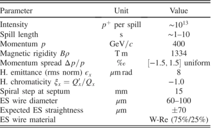
TABLE I. Accelerator and ES parameters for slow extraction at SPS.
Parameter Unit Value
Intensity pþper spill ∼1013
Spill length s ∼1–10
Momentump GeV=c 400
Magnetic rigidityBρ T m 1334
Momentum spreadΔp=p ‰ ½−1.5;1.5uniform H. emittance (rms norm)ϵx μm rad 8
H. chromaticityξx¼Q0x=Qx −1.0
Spiral step at septum mm 15
ES wire diameter μm 60–100
Expected ES straightness μm 70
ES wire material W-Re (75%/25%)
FIG. 2. Spread in particle positions caused by scattering at a diffuser upstream of the ES, after a suitable phase rotation.
βrctransiting a lengthldof material with radiation lengthX0 is parameterized as[16]
θMC≈13.6 pβr
ffiffiffiffiffiffi ld
X0 s
1þ0.038lnld
X0
mrad: ð1Þ
Nuclear scattering will produce single-scatter angles via elastic scattering or will result directly in beam losses from inelastic processes. For the SPS, ionization energy loss
−ΔE=E is a few 10−5 and was not considered.
The location of the diffuser determines the extent to which the angular scattering is transformed into positional spread at the ES. Two different diffuser configurations have been considered—local, where the diffuser is inside the extraction bump, ornonlocal,where the diffuser is not in the same betatron period as the ES. This requires a separate closed-orbit bump and separate instrumentation and is sensitive to optics changes between the diffuser and ES.
The local configuration is easier to set up and keep stable in operation but is more constrained in the choice of phase advance to the ES.
The required MC scattering angle and, hence, diffuser length for different materials were estimated in a first rough approximation, under the assumptions of the same horizon- tal beta function βx at the diffuser and ES which are separated in the horizonal phase byδμx, that the scatterer has negligible length and that the ES losses are dominated by head-on impacts with a small transverse angle. An rms scattering angle θMC at the diffuser is transformed into a position spread at the ES after a phase advance δμx of βxsinδμxθMC, and for a diffuser width of wd (with asso- ciatedσxofwd= ffiffiffiffiffi
p12
), the resulting rmsσxESof the position spread at the ES is
σxES≈ ffiffiffiffiffiffiffiffiffiffiffiffiffiffiffiffiffiffiffiffiffiffiffiffiffiffiffiffiffiffiffiffiffiffiffiffiffiffiffiffiffiffiffiffiffi β2xsin2δμxθ2MCþw2d=12 q
: ð2Þ For the prototype feasibility study in the SPS, a location upstream of quadrupole QFA.216 was chosen with3.8° s of phase advance to the ES andβxof about 95 m. With initial design assumptions of200-μm-wide ES and250-μm-wide diffuser, then from the basic analytical estimate the diffuser needs to produce an angle of around25μrad to produce a position spread with σx≈0.15mm to reduce the density at the ES by a factor of 2, neglecting separatrix angular spread and ES length. At400GeV=c, this corresponds to 0.58 radiation lengthsX0.
The diffuser length needed to produce this specific MC scattering angle depends strongly on the material. This is important for the overall performance, since the probability of a nuclear scattering, as defined by the nuclear collision length λn, scales differently with the length to the MC scattering angle[17]. For the diffuser, specifically the ratio of radiation length X0to the nuclear interaction length λi should be as small as possible, since largeλiminimizes loss
through inelastic nuclear scattering, while short X0 max- imizes the MC scattering angle.
A comparison of materials and diffuser lengths needed to achieve25μm rms MC scattering angleθMCat400GeV=c is shown in TableII. The loss quoted includes only protons undergoing inelastic nuclear scattering in the diffuser: In reality, the actual loss is slightly higher, as a fraction of the elastically scattered protons with rms angleθe(representing 30%–40% of the nuclear collisions) will also be lost on the accelerator aperture.
From these considerations, denser materials should be better than low-Z ones, with tungsten-rhenium alloy (WRe), Ta, and Mo all giving similar results. WRe, which is widely used for ES wires, provides over a factor of 10 gain in the loss per impacting proton generated at the diffuser itself when compared to materials with a lower atomic number such as carbon.
IV. ANALYTICAL MODEL
An analytical model[18]was developed from geometric considerations and scattering formulas, to allow detailed analytical estimates of required lengths and performances.
The full details of the model are given in the Appendix.
The model calculates the losses in the diffuser, on the aperture, and on the ES wires. It takes into account the nuclear scattering on the diffuser, the separatrix presenta- tion, and angular spread, as well as the effects of the beam momentum, diffuser material, diffuser and ES widths, and relative offset. The basic accelerator transverse parameters are also included. Despite some simplifying assumptions (ES as a black absorber with no E field and zero length), this model captures the basic dynamics and allows full parametric exploration of dependencies on the key param- eters like diffuser length, width, phase advance, material, and beam momentum.
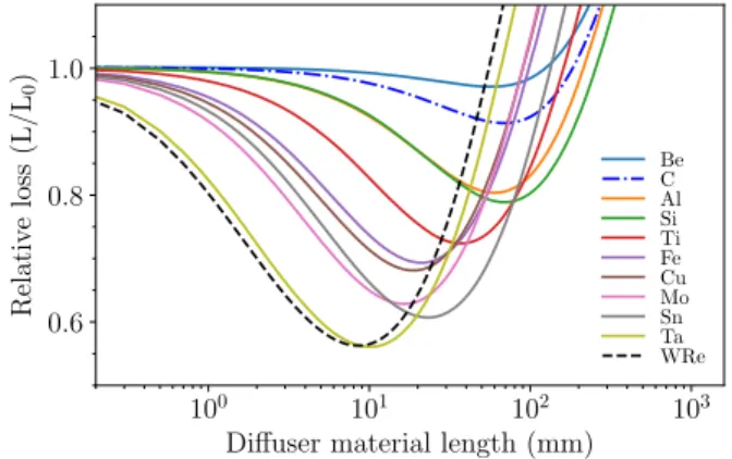
For the purposes of the SPS, the calculated total loss reduction with different diffuser materials was checked with this model. The relative loss, as calculated from the ratio of total lossLwith a diffuser to loss without a diffuser L0, as a function of the diffuser material and length is given TABLE II. Diffuser length needed to achieveθMC ¼25μrad MC scattering of400GeV=cprotons, for materials with a range of scattering characteristics.
Parameter 94Be 126C 2814Si 9642Mo 18173Ta 18474.3WRe Densityρ[g=cm3] 1.8 2.0 2.3 10.2 16.7 19.7 λn total [cm] 29.9 29.6 30.2 9.1 6.6 5.6 λi inelastic [cm] 42.1 42.9 46.5 15.3 11.5 9.8 Rad. lengthX0 [cm] 35.3 21.4 9.4 0.96 0.41 0.35 Elastic ang.θe [μrad] 237 215 162 108 87 87 Diffuser length [cm] 20 12 5.5 0.55 0.23 0.19
−ΔE=E[10−4] 3 2 0.9 0.4 0.2 0.2 Inelastic loss [%] 38 24 11 3.5 2.0 1.9
in Fig. 3, while in Fig. 4the relative loss at the optimum length is plotted as a function of mass number A for each material. The advantage of high-Z material is clear as is the gain expected from this model with lower beam momen- tum; see also [5].
A simple scaling of the diffuser performance with beam momentum was tried using the analytical model, with some reasonable assumptions made on the scaling of the β functions and separatrix angular spread with momentum, for a constant ES width of 0.2 mm and a diffuser width of 0.25 mm. From the results (Fig. 5), the diffuser should become more effective at lower energies[5,19], although with the very large scattering angles the losses on other elements in the extraction region and transport will need to be considered, as well as ionization energy loss. Also notable is that for slow extraction above 1TeV=c [20]the diffuser becomes inef- fective, with no loss reduction seen for any length.
V. NUMERICAL SIMULATIONS
Numerical macroparticle tracking simulations were made to evaluate the diffuser performance as a function
of the parameters and to compare with the analytical estimates and experimental results. A 2DPYTHONtracking routine was used initially. The tracking included tune sweep, sextupoles, scattering at the diffuser, and ES, but no chromatic effects. The diffuser was modeled as a full density blade, and the ES as a single, full blade with reduced density calculated from the total material, overall length, and assumed width.
In addition, for benchmarking the 2D simulations and to investigate the nonlocal configuration, a complete 5D (rf off) polymorphic ray tracing was developed in sector maps exported fromPTC [21]with the codePYCOLLIMATE[22], using the same techniques described in Ref.[23].
The parameters used in the simulation for the accelerator and ES configurations for the simulations (and also the analytical estimates) are shown in Table III. The results were normalized to the total losses with no diffuser present at the optimum ES angle. The simulated extraction process was adjusted to give the 12μrad (1σ rms) operational separatrix angle spread at the ES. Before the diffuser was implemented, the angle of the ES was scanned in the simulation, to find the optimum ES angle with minimum loss on the ES for a specific extraction separatrix, as is done periodically in operation with the real system.
For the initial assumptions of 0.2 mm ES width, a WRe diffuser length of about 4 mm with a width of250μm was proposed (Fig. 6), giving a reduction in the total loss of FIG. 3. Analytical calculation of the relative total loss for
different diffuser lengths and materials, for 0.25 mm diffuser width, 0.2 mm ES width, 3.8° phase advance, and 400GeV=c protons.
FIG. 4. Analytical calculation of the optimum relative total loss with a diffuser as a function of diffuser atomic number A, for 100 and 400GeV=c protons.
FIG. 5. Analytical calculation of the relative total loss for different diffuser lengths and a range of beam momenta, for a 0.2-mm-wide ES and 0.25-mm-wide WRe diffuser and 3.8°
phase advance.
TABLE III. Parameters assumed for diffuser optimization.
Parameter Value
Beam momentump[GeV=c] 400
βx (ES and diffuser) [m] 94
Phase advance diffuser to ESδμx [degree] 3.8
ES total length [m] 17.25
ES field [MV=m] 11.0
Separatrix rms angular spreadσ¯px [μm] 12
40%. The loss profile is distinctive with peaks on either side of the minimum, where the losses increase to about 25%
higher than without a diffuser. The extra losses from the diffuser in a beam, but far from the optimum position, are around 5%. The positioning accuracy of the diffuser needs to be better than50μm, as evidenced from the narrow- ness of the minimum in the loss response. The error bars shown are the calculated statistical uncertainty in the relative loss arising from the limited number of macro- particles in the simulation.
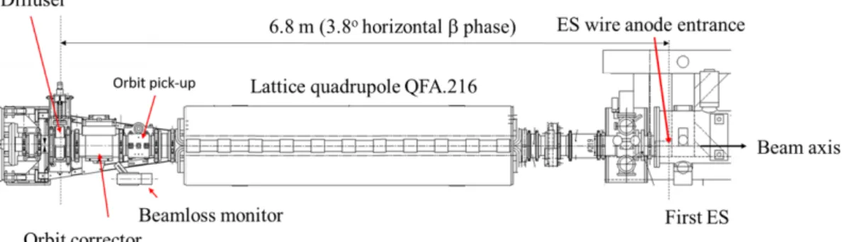
VI. PROTOTYPE SPS DIFFUSER DESIGN For the diffuser beam tests in the SPS, the local configu- ration was chosen with the diffuser upstream of QFA.216 at a phase advance of 3.8° from the ES entrance (Fig.7). The diffuser specification was confirmed by the particle tracking simulations, with an ES width of200μm assumed from the ES wire diameter and known anode tolerances.
The prototype diffuser unit was built in collaboration with the Wigner Research Centre for Physics, Hungary.
Instead of tungsten-rhenium alloy, tantalum wire of
∅200μm was finally used for the diffuser material to achieve the specified straightness; the Ta wire proved much
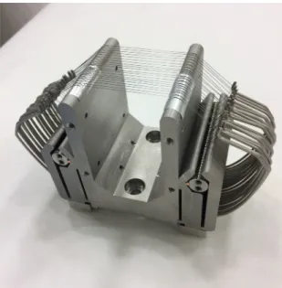
more malleable than the originally sourced∅250μm WRe wire, which was too stiff to mount correctly. The mounted Ta wire array had a final∅260μm effective width, which was obtained by offsetting half of the wires with a60μm Al foil shim (Fig. 8) to be as close as possible to the specified250μm width. The mechanical design of the wire array is shown in Fig.9.
The simulations assumed a rectangular diffuser of uni- form reduced density, while the prototype used discrete circular section wires. This will give a larger density on the diffuser axis and a lower density at the edges—the effect of this was not taken into consideration in the estimated performance. It could be evaluated with a more sophisti- cated simulation.
As a scatterer, the performance of Ta is similar to WRe in terms of the diffuser loss produced for a given scattering angle (TableII). The reduction in the effective length of the diffuser due to the smaller wire diameter results in a lower gain in total losses, to about 38% (Fig.10). The diffusers are both assumed to have 20 wires, of ∅250μm for the WRe version and ∅200μm for the Ta version, with the offset mentioned above. The Ta version is slightly less effective in the simulation.
The total loss response in the simulation and the analytical estimate are insensitive to the diffuser angle, as long as the angle error with respect to the beam remains below about 1 or 2 mrad—it was therefore decided to install the diffuser prealigned to an angle of 1.7 mrad, which is the approximate angle of the extracted beam at the diffuser location.
A single degree of freedom was allowed for translation of the wires in and out of the beam with a precision thread, driven by a stepping motor permitting a step size of5μm,
FIG. 7. Integration of the prototype diffuser in SPS, upstream from the electrostatic septum ES and focusing lattice quadrupole QFA.216.
FIG. 6. 2D simulated and analytical estimates for total 400GeV=c beam loss (normalized to the no diffuser case) vs the diffuser position for a 0.2-mm-wide ES, for a WRe diffuser made of 20 wires of∅250μm.
FIG. 8. Schematic (not to scale) of shimming of Ta diffuser wires with thin Al foil.
keeping the angle fixed. The overall object is very compact, with only 187 mm in total occupied in the lattice including vacuum flanges.
After fabrication, cleaning, and acceptance tests, the diffuser was installed in the SPS ring at the end of 2017.
Extra LHC-type beam loss monitors (BLMs) were also added, next to the diffuser itself and partway along the ES, to improve the temporal resolution and dynamic range of the beam loss measurement.
VII. EXPERIMENTAL RESULTS
SPS beam tests were made in 2018 with scans of the diffuser position in front of the ES wires, initially with a
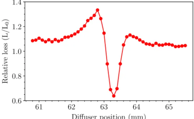
low intensity of2×1012 protons per spill. The results were immediate and highly reproducible, with a reduction of 15% in the total beam loss on the ES (summed over all extraction BLMs) at the optimum position, compared to extraction with no diffuser. Measured loss response profiles are shown in Fig. 11, for position scans made with two different low-intensity beams. The error bars are the standard deviation of the loss measurements accumulated at the same diffuser position.
The specified (and achieved) positioning accuracy of the diffuser of 50μm was confirmed to be necessary and attainable with the positioning mechanism and control.
The diffuser was also deployed for a 23-hr period on the operational beam, with3×1013 protons extracted per spill.
It took 3 min to move the diffuser to the operational position and 22 min to optimize the position with respect to the beam.
There was a short initial period of outgassing when the wires were moved into the beam, where the vacuum pressure increased from1×10−8to2×10−7 mbar, but this recov- ered within about 15 min. The measured loss remained stable over the full period, although the total loss reduction factor was lower than for the low-intensity beam, at about 10%, possibly due to the larger separatrix angular spread at the ES with high intensity (see below) or to intrinsic angular misalignment of the ES due to the long interval (several months) since a full overall ES angle realignment.
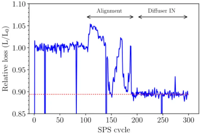
In this test, a total of1.2×1017 protons were extracted with the diffuser in a beam. The normalized sum of all SPS BLMs before, during, and after the alignment are shown in Fig.12. The stable reduction in beam loss is visible after the alignment period. Because of time constraints, it was not possible to realign the ES girder to optimize the losses or to deploy the newly developed constant optics extraction for reduced separatrix angular spread[11], and some further improvement of the diffuser performance may have been possible.
The response of the loss monitor BLM.216 located at the diffuser is not much affected by showering losses from the ES. With a diffuser in a beam, the monitor reading per FIG. 9. SPS diffuser wire array, comprising 20 Ta wires of
∅200μm individually tensioned with springs and aligned in two sections with a60μm offset. The wires are spaced by 1.5 mm for a total array length of 30 mm.
FIG. 10. 2D simulated normalized400GeV=ctotal beam loss vs diffuser position for a200-μm-wide ES, comparing a250-μm- wide WRe diffuser made of ∅250μm wires and a Ta diffuser made of∅200μm wires with half offset by60μm.
FIG. 11. Measured sum of extraction beam losses (normalized to losses with no diffuser present) for diffuser position scans with two different intensity beams.
extracted proton increased by a factor of 7.5, albeit from very low levels. This is a slight concern, since this zone is a
“low-dose”area used for access during interventions on the much more radioactive ES. Although the expected remnant dose at the diffuser is expected to be more than an order of magnitude less than the ES, the increase in this previously low-radiation area needs to be taken into consideration in the overall optimization.
VIII. COMPARISON WITH SIMULATIONS AND ANALYTICAL ESTIMATES
The measured results gave a much lower loss reduction than expected from the analytical approach and simulations with the initially assumed parameters. A number of unknown factors influence the simulated profile, chiefly, the alignment of the ES relative to the beam, the ES width, and the separatrix width and distribution (quantified by the third and fourth standardized central moments of the angular distribution at the ES).
The 2D simulations were used to match the measured results by varying the ES width, ES angle, and separatrix rms angular width. The ES angle, width, and separatrix rms angular width were treated as hyperparameters in a numerical regression optimization routine, while the third and fourth moments of the distributions were not con- trolled. The optimization was made using the Powell algorithm[24], with the simulation rerun each time inside the optimizer loop and the residual between normalized measurement (with total loss data averaged at each diffuser position) and simulation losses used as an objective function. The optimizer converged to an ES alignment 50μrad from the“minimum loss”position and an ES width of520μm, with a separatrix rms angular width of8.9μrad, lower than the 12μrad found in fullPTCsimulations[11]
for the nominal beam but qualitatively consistent with the reduced spread expected at a lower intensity.
For the analytical estimate, a similar approach yielded an ES width of 420μm and a separatrix width of 6.0μrad,
which seems slightly less realistic. With this approach, the details of the profile did not match the measured data very well, and the derived separatrix angular spread has to be treated with a lot more caution, since the analytical formulation used actually breaks down for a narrow separatrix angular spread, discussed below.
The comparison between normalized total loss in sim- ulation and measurement for these derived parameters is shown in Fig.13. The analytical model does not capture the asymmetry of the loss response—this is better reflected in the numerical simulation, where the separatrix density is not uniform and also where the ES field, misalignment, and finite length are included.
The source of the asymmetry is important to understand— from thePTC results, the higher total loss peak at a lower diffuser position is consistent with a well-aligned ES (as in the simulation). Referring back to Fig.2, it can be appreciated that, if the separatrix angle at the ES has too low an angle with respect to the ES alignment, this will depopulate the loss peak at the diffuser position lower than the optimum and overpopulate the peak at a higher than optimum diffuser position. In addition, it was also found that the detailed density distribution in the separatrix plays an effect, since an extraction process (or simulation) which skews the distribu- tion to high (or low) angles will produce more losses on the peak to the lower (or higher) side of the optimum, respec- tively. It should be possible to confirm this experimentally by measuring the distributions as a function of ES misalign- ment. In Fig.13, the 2D simulated losses could be made to match the experimental data by varying these factors—this was not attempted for the full 5D simulations.
The main, and important, overall conclusion is that this inferred ES width of≈400–500μm is significantly larger than was expected from the wire diameter and individual anode straightness. In addition, the results indicate that the separatrix angular spread needs to be well controlled.
To illustrate the dependence of the agreement with the simulation on the ES width, the measured and simulated FIG. 12. Normalized SPS beam loss (sum on all BLMs around
the full ring) spanning 300 cycles (about 3 hr) around the insertion of the prototype diffuser into the operational beam.
FIG. 13. Comparison of400GeV=cmeasured normalized sum of extraction BLM loss to simulated and analytical losses for a 260μm Ta diffuser with1012protons per extraction.
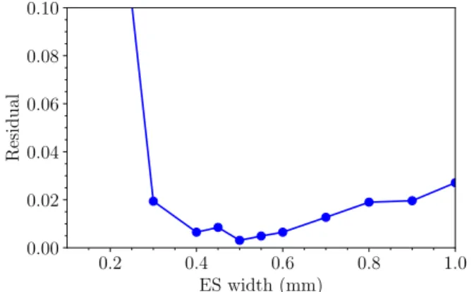
curves (total loss vs diffuser position) were compared, as a function of the simulated ES width, for a fixed separatrix width of8.9μrad. Figure14plots the residual of the best fit between the measured data and simulated data as a function of the simulated ES width, for a simulated separatrix width of8.9μrad. The minimum is rather broad, but the ES width of400–600μm fits best the measured data, which is also consistent with the analytical result of 420μm. More importantly, it agrees with the completely independent estimate of 500μm obtained with the crystal shadowing experiment also performed in 2018 [9].
The effect of the separatrix angular spread on the modeled diffuser effectiveness was investigated by modi- fying the separatrix width in simulation and analytically, for the inferred ES widths. The total losses without a diffuser (which in the simulation also will change with the sepa- ratrix angular spread) were compared to the minimum obtained when scanning the diffuser position (Fig. 15).
The absolute total loss level changes only by a few percent with the larger separatrix width, which is consistent with the large ES width for an ES well aligned with the beam. The diffuser efficiency is seen to drop with an increasing separatrix width. Important differences between
the analytical model and the simulations are apparent at low and high angular spread. This is almost certainly due to the approximations used in the analytical approach to calculate the losses on the ES wires, which convolutes the rms angular spread with the MC and elastic scattering angles and also which assumes a uniform density.
Although the scalings cannot be taken as absolute, the trends in the simulation are clear, and a total loss reduction of 0.9 for large (12–15μrad) and of 0.85 for narrower (6–10μrad) looks reasonable, which could explain the reduction in diffuser efficiency observed experimentally with high intensity.
To further investigate this important effect, a detailed study with more realistic separatrix distributions would be needed. The criticality of good separatrix angular control (i.e., narrow spread and high stability) is highlighted by this result, reinforcing the importance of the ongoing improve- ments in the control of the separatrix stability and spread being pursued at the SPS.
IX. OPTIMIZING SPS DIFFUSER CONFIGURATION AND PERFORMANCE The experimental results showed that the diffuser tested with a beam was too narrow for the actual operational ES width, resulting in the best-case total loss reduction of 15%.
Simulations and the analytical model both show that the diffuser width needs to be matched precisely to the ES width, to obtain the optimum loss reduction: Too narrow and unscattered particles will directly impact the ES; too wide and the losses from nuclear scattering in the diffuser are unnecessarily large, and particles which would other- wise avoid the ES can be scattered back into the ES wires.
For the inferred ES width of 500μm and 3.8° phase location, another set of parametric scans was made to find the optimum configuration. A 5-mm-long WRe diffuser with a width of550μm would allow about 27% total loss reduction, assuming the separatrix width is kept at12μrad.
Figure16illustrates the expected total loss response from FIG. 14. Residual between measured and best-fit 2D simulated
normalized total loss as a function of the ES width.
FIG. 15. Relative total beam loss for a260-μm-wide Ta diffuser and500-μm-wide ES, as a function of the separatrix rms angular spread.
FIG. 16. 2D simulated and analytical relative total loss as a function of the diffuser position, for550μm diffuser width and a length of 5 mm.
such a diffuser. Materialwise, Ta should provide almost as good performance as WRe and may be preferred for mechanical reasons.
Another improvement could be obtained through also optimizing the phase advance, using either a local or a nonlocal configuration. This would be simple to integrate, given the very small footprint of the physical diffuser device, but for the nonlocal option the diffuser needs to be in a location where an extraction bump can be applied, to allow enough aperture for the diffuser to remain in position when the beam is injected. The alternative would be to move the diffuser in the beam each cycle or to apply an opposite-sign injection bump, neither of which is consid- ered practical.
For the local case, different phase advances δμx were tested in the simulation with the simplifying assumption that the required diffuser width at a location with a beta function of βdiff is 550μmðβdiff=βESÞ1=2=cosδμx for a constant WRe diffuser length of 5 mm (neglecting the αsinδμx term). The analytical approach was also com- pared, but in this case with the optimum diffuser width obtained from a scan at each phase advance.
The obtained total loss reductions as a function of the phase advance is plotted in Fig. 17. The results start to diverge for higher phase advances but do allow one to conclude that a total loss reduction of about 35% could be obtained for an optimum phase advance of about 10°, for a diffuser width of about450μm. This location in the SPS is between two dipole magnets, another 7 m upstream of the present diffuser location.
The nonlocal configuration was also tested with the complete simulation approach using full 5D particle tracking with PTC and PYCOLLIMATE. This was done to cross-check the simpler local diffuser tracking results and also because in the nonlocal configurations studied the nonlinearities between the diffuser and ES are seen to modify the dynamics significantly. In these simulations, the chromatic behavior was also taken into account. This was also found to play an important role, since important
differences in dispersion at the diffuser and ES will also cause a reduction in the diffuser efficiency, adding another effect which causes unscattered particles to impact the ES directly and reducing the efficiency.
Available locations were studied in different straight sections in the SPS, with an optimization at each location of the diffuser width and length. The best result was obtained for a location in LSS6 (where extraction bumpers exist). A total loss reduction of 35% was obtained with a 7-mm-long,400-μm-wide Ta diffuser (Fig.18).
X. CONCLUSIONS
A passive diffuser to reduce extraction beam loss was simulated, designed, built, installed, and tested successfully in the SPS, both in dedicated MD and for almost 24 hr with a high-intensity operational400GeV=cslow extracted pro- ton beam. A significant and reproducible reduction in the total beam loss was observed. For a low intensity, the loss reduction was 15%, consistent with an ES width of about 500μm and a separatrix angular spread in the range of 6–9μrad. For a high intensity, the diffuser was deployed for 24 hr on the operational beam and a 10% reduction of slow extraction beam loss, with no impact on losses in the transfer lines or at the experiments. The lower total loss reduction factor could be explained by the larger separatrix angular spread (expected to be about12μrad) at a higher intensity.
The alignment of the device was easy and the stability in operation excellent. Given the simplicity of the technique and of the associated hardware, the use of a diffuser alone or in combination with other loss reduction techniques such as phase space folding with octupoles or crystal shadowing promises a solid means of substantial slow extraction loss reduction. For the SPS, a diffuser optimized for 500μm ES effective width with12μrad separatrix angular spread could reduce the total extraction losses by approximately 35% in a local configuration with about 10° phase advance and by the same amount for a nonlocal location in LSS6.
As part of this work, simulation methodologies using simple 2D tracking and complete 5D PTC tracking have FIG. 17. 2D simulated and analytical relative total loss reduc-
tion as a function of the phase advance between the diffuser and ES, for WRe diffuser length 5 mm.
FIG. 18. Simulated (full 5D PTC) relative total loss for a nonlocal diffuser 7 mm long,400μm wide in LSS6.
been used. An analytical description has also been devel- oped which allows a fast optimization of initial parameter choices for a specific configuration (beam momentum, septum width, lattice location) as a basis for detailed (and possibly automatic) numerical optimization.
The application of the diffuser technique to other energies is possible. For lower energies, the diffuser should become more effective, where the shorter and thinner ES together with increased MC scattering angles may allow better loss reductions to be achieved. Conversely, at higher energies, the reduction in the MC scattering angle for a given length means that the diffuser becomes less effective.
Overall, the results from the SPS confirm the validity of the technique. The measurements and simulations have also given valuable information about the unexpectedly large ES width and highlight that the other key aspect to improve the performance is the effective separatrix angular spread.
ACKNOWLEDGMENTS
The authors thank the CERN PS and SPS operations teams for assistance in preparing and carrying out the beam tests and for the provision of the special beam used. Thanks are also due to the many CERN colleagues who assisted with the integration, testing, and installation of device. Finally, fruitful discussions with V. Nagaslaev, R. Muto, and M.
Tomizawa on the diffuser concept and its application are gratefully acknowledged. The collaboration with the Wigner Research Institute for Physics was made possible by the Hungarian National Research, Development and Innovation Office, Grant No. K124945.
APPENDIX: ANALYTICAL LOSS MODEL Normalization of position and angle coordinates is made to ease some of the transformations. The normalizations are x¼x¯ ffiffiffiffiffiffiffiffiffiffiffiffiffi
βN=βx
p and px¼x¯ ffiffiffiffiβN
βx
q αxþpx
ffiffiffiffiffiffiffiffiffiffi βNβx
p , where x¯ andpxare the unnormalized values. For the SPS, the factor βN ¼94m (the beta function at the ES septum entrance) is used to give normalized values in millimeter or mrad at the ES which are equal to real millimeter offsets.
For changes in angle δθ at constant x, e.g., through scattering, the angle normalization reduces toδθ¼δθ¯ ffiffiffiffiffiffiffiffiffiffi
βNβx
p .
1. Losses on ES wires without a diffuser The particle density is assumed uniform both along the separatrix and across its thickness. The ES is assumed to be a black-box absorber, such that all impacts result in the particle being lost.
Under the above assumptions, for a normalized ES width of ws and separatrix thickness h, the number of particles lost isL0¼hsinϕws
s (Fig.19), where ϕs is the presentation angle of the separatrix at the ES in normalized phase space with respect to the px axis. L0 is the reference for
normalizing all subsequent losses. Note that, with phase advanceδμx between the diffuser and septum, the separa- trix presentation angle at the diffuser isϕs−δμx, since in the normalized system the transport between two locations is a simple clockwise rotation of the particle coordinate by the corresponding phase advance.
2. Losses on a diffuser
An upstream diffuser at a phase advance of δμx from the ES with normalized widthwd intercepts a number of particlesNd¼hsinðϕwsd−δμxÞ. For a diffuser lengthld, only a fractionFi¼ ½1−expð−ld=λiÞare directly lost as a result of inelastic scattering. The direct absolute loss at the diffuser is thenLd¼NdFi, expanded as
Ld¼NdFi¼h wd
sinðϕs−δμxÞ½1−expð−ld=λiÞ: ðA1Þ
3. Scattering through a diffuser
The surviving particles will have a distribution of angles given by their initial distribution (the angular width of the separatrix) and the scattering processes undergone. These are multiple Coulomb and elastic nuclear, characterized by the rms scattering angle projected onto one transverse plane ofθMC andθe, respectively.
From the literature [15,16], one can readily find the expressions for these rms angles—for a material with radi- ation lengthX0and a beam momentumpin GeV=c, after normalization the MC scattering rms angle can be written as
θMC≈ ffiffiffiffiffiffiffiffiffiffi βNβd
p 13.6
pβr ffiffiffiffiffiffi
ld X0
s
1þ0.038lnld X0
m:mrad: ðA2Þ FIG. 19. Idealized separatrix in normalized phase space at ES, where the number of particles impacting the front of the septum is determined by the ES width, separatrix thickness, and the presentation angle of the separatrix.
The normalized rms elastic scattering angle depends on the material mass numberAas well as the beam momentum pin GeV=c and is described by[25]
θe≈ ffiffiffiffiffiffiffiffiffiffi βNβd
p 197
A1=3pm:mrad: ðA3Þ The absolute number of scattered (MC and elastic) particles which exit the diffuser is just Ndexpð−ld=λiÞ. Of these, a fraction Fe ¼ ½1−expð−ld=λeÞ will have undergone elastic scattering in addition to MC scattering, while the remaining fraction expð−ld=λeÞare subject only to MC scattering.
This allows us to write down the absolute numbers of particles NMC undergoing MC scattering alone, and the numberNe which have also been elastically scattered, as NMC¼h wd
sinðϕs−δμxÞexpð−ld=λiÞexpð−ld=λeÞ; ðA4Þ Ne¼h wd
sinðϕs−δμxÞ½1−expð−ld=λeÞexpð−ld=λiÞ: ðA5Þ
4. Losses on an aperture
To account for the fact that some of the elastically scattered particles have big angles and will be lost locally or in the subsequent transfer or accelerator turn, an aperture limit is defined by the normalized accelerator acceptanceA. A particle scattered by a normalized angleθwill be lost if θ> A. This is somewhat complicated to evaluate, since both planes should be taken into account, which have different acceptances and also different betas at the diffuser—an approximation was made by using the minimum of the H and V acceptances and the beta value for the corresponding plane. If we consider that the SPS aperture or downstream transfer line aperture is about20mm at a location with beta function β of 109 m, this gives an acceptance of about 18.5 mrad in normalized angle, which is somewhat pessimistic.
The aperture losses La are defined as any particles scattered with an angle larger than this limit A, i.e.,
La¼Ne
1− 1 ffiffiffiffiffiffiffiffiffiffi 2πθ2 p
Z −A
A
exp
− x2 2θ2
dx
¼Neerfc
A
θ ffiffiffi p2
; ðA6Þ
where θ¼ ffiffiffiffiffiffiffiffiffiffiffiffiffiffiffiffiffiffi θ2eþθ2MC
p (neglecting the intrinsic angular spread).
5. Position spread at ES from diffuser scattering The key part of the diffuser performance is that the rotation by phase advanceδμxto the diffuser of the scattered distributions initially of widthwdand angular spreadsθeand
θMC produces new distributions in x of which only the central part intersects the ES, while the larger scattered amplitudes escape impact. The positional spread in the scattering terms are just the rotation of the scattering angle to the ES location through the phase advanceδμx: σxMC¼θMCsinδμx; σxe¼ ffiffiffiffiffiffiffiffiffiffiffiffiffiffiffiffiffiffi
θ2eþθ2MC
q
sinδμx: ðA7Þ
6. Losses on ES wires
The losses at the ES can be split into three parts: LMC
from the MC scattered particles from the diffuser,Le from the elastically scattered particles, and (importantly) LU
from the unscattered edges of the separatrix. These impacts arise either from a diffuser misalignment or width mis- match and to the (normalized) finite angular spread of the separatrixσpx at the ES.
The losses from the scattered distributions can both be treated the same way: In the following, the subscriptsMC andeare dropped until the final expressions.
a. Losses on ES wires from scattered distributions The scattered distribution is transported to the ES with a convolution of the uniform (diffuser width) and Gaussian (scattering) distributions.
In general, the probability density function (PDF)PðxÞ for the convolution of a uniform distribution of unity height betweena < bwith a Gaussian of meanμand sigmaσat a locationxis given by
PðxÞ ¼ 1 ðb−aÞ ffiffiffiffiffiffiffiffiffiffi
2πσ2 p
Z aþμ
bþμ exp
−ðτ−xÞ2 2σ2
dτ
¼ 1
2ðb−aÞ
erf
x−ðμþaÞ ffiffiffiffiffiffiffi 2σ2 p
−erf
x−ðμþbÞ ffiffiffiffiffiffiffi 2σ2 p
: ðA8Þ For a diffuser width wd projected to the ES location of wdESand the distributionσxESinxat the ES from diffuser scattering given by σxMC or σxe, respectively, from Eq.(A7), we find for the PDF at the ES
PðxÞ¼ 1 2wd
erf
xþwdES=2 ffiffiffiffiffiffiffiffiffiffiffi 2σ2xES p
−erf
x−wdES=2 ffiffiffiffiffiffiffiffiffiffiffi 2σ2xES p
: ðA9Þ
From this PDF, we can express the lossesLMCorLeon an ES with widthws and offset xo:
L¼h Z x
oþðws=2Þ xo−ðws=2Þ PðxÞdx
¼ h 2wd
Z x
oþðws=2Þ xo−ðws=2Þ
erf
xþwdES2 ffiffiffiffiffiffiffiffiffiffiffi 2σ2xES p
−erf
x−wdES2 ffiffiffiffiffiffiffiffiffiffiffi 2σ2xES p
: ðA10Þ
SinceR
erfðzÞdz¼zerfðzÞ þep−zffiffiπ2, we can now write the full expression for this loss component as
L¼ N 2wd
I
x1
2σ ffiffiffi p2
−I x2
2σ ffiffiffi p2
−I x3
2σ ffiffiffi p2
þI
x4
2σ ffiffiffi p2
; ðA11Þ
whereIðzÞ ¼zerfðzÞ þep−zffiffiπ2and the horizontal coordinates x1−x4 are given by
x1¼2xoffþwsþwdES; x2¼2xoffþws−wdES; x3¼2xoff−ws−wdES; x4¼2xoff−wsþwdES: The two contributions LMC and Le from MC and elastic scattered particles are obtained by using the specific values forNMC; NeandσxMC;σxein place ofNandσ, respectively, in Eq.(A11).
b. Losses on ES wires from unscattered particles The final part of the losses on the ES wires are from particles which are not scattered on the diffuser. This is defined by the separatrix angular distribution (width) at the ES, the gap cut by the diffuser (Fig. 20), and the phase advance between the diffuser and septum.
For the simplifying assumption of uniform separatrix density (which will tend to overestimate this component), the particles not cut by the diffuser which still impact the ES can be derived from geometrical considerations of the rotated triangular edges of the separatrix which intercept the ES. The losses for an ES offset ofxoffwith respect to the center of the diffuser shadow produced by the diffuser of widthwdES at the ES location is given by
LU ¼ ½ðL1−L2Þ−ðR1−R2Þ; ðA12Þ
where for the values
a¼ ðxoffþwdESÞ=2; c¼ h sinϕ; σf¼nσpxsinδμx; p1¼xoffþws=2;
p2¼xoff−ws=2
we have the expressions for the contributing components:
L1¼min
c
2σfðmax½p1−ða−σfÞ; 0Þ2; c 2σf
þcmax½p1−a; 0;
L2¼min
c
2σfðmax½p2−ða−σfÞ; 0Þ2; c 2σf
þcmax½p2−a; 0;
R1¼min
c
2σfðmax½−p1−ða−σfÞ; 0Þ2; c 2σf
þcmax½−p1−a; 0;
R2¼min
c
2σf
ðmax½−p2−ða−σfÞ; 0Þ2; c 2σf
þcmax½−p2−a; 0: ðA13Þ
FIG. 20. Normalized phase-space representation at ES, after phase rotation throughδμx.
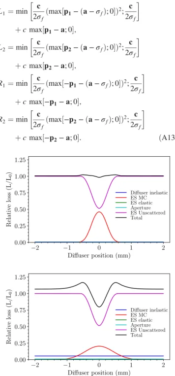
FIG. 21. Analytical estimates of 400GeV=c normalized loss contributions vs diffuser position for a 0.5-mm-wide ES and 0.25 mm WRe diffuser, with length of 1 (upper) and 10 mm (lower).
7. Total losses
The total losses on the diffuser, the aperture, and the septum wires are then simply the sum of the separate components:
LTot ¼LdþLaþLeþLMCþLU: ðA14Þ The different contributions to the total losses are instruc- tive: In Fig.21are plotted all of the individual contributions plus the total, for the SPS with 0.5 mm ES and 0.25 mm diffuser, for two diffuser lengths of 1 and 10 mm. The short diffuser shows how the model starts to break down at a very short length, since the two contributions do not exactly cancel, while for the 10 mm diffuser the distribution for the MC (and elastic) component illustrates how the principle is working.
The IPython notebook for the model is available at Ref. [18].
[1] A. Golutvinet al., A facility to search for hidden particles (SHiP) at the CERN SPS, Report No. CERN-SPSC-2015- 016 (SPSC-P-350), CERN, Geneva, 2015.
[2] C. C. Ahdida, M. Calviani, B. Goddard, R. Jacobsson, and M. Lamont, SPS beam dump facility comprehensive design study, Report No. CERN-PBC-REPORT-2018-001, CERN, Geneva, 2019.
[3] A. Durand, On the scattering of protons at 400 GeV in a wire array placed at the front of an electrostatic septum, Nucl. Instrum. Methods127, 349 (1975).
[4] A. Durand, Efficacitie d’un r´eseau de fils plac´e devant la plaque du septum du transfer continu a12GeV=c (private communication with C. Germain).
[5] B. Goddardet al., Optimization of diffuser (pre-scatterer) configurations for slow extraction loss reduction at electro- static septa, in Proceedings of the 9th International Particle Accelerator Conference, Vancouver, Canada (JACoW Publishing, Geneva, Switzerland, 2018), pa- per TUPAF053, pp. 830–833.
[6] B. Goddard, B. Balhan, J. Borburgh, M. A. Fraser, L. S.
Stoel, and F. M. Velotti, The use of a passive scatterer for SPS slow extraction beam loss reduction, in Proceedings of the 8th International Particle Acceler- ator Conference, Copenhagen, Denmark(JACoW Pub- lishing, Geneva, Switzerland, 2017), paper MOPIK044, pp. 607–610.
[7] V. Nagaslaev and I. Rakhno, MARS tracking simulations for the Mu2e slow extracted proton beam, inProceedings of the 6th International Particle Accelerator Conference, Richmond, VA, USA (JACoW Publishing, Geneva, Switzerland, 2015), paper THPF125, pp. 4010–4012.
[8] M. A. Fraseret al., Improvements to the SPS slow extraction for high intensity operation, Report No. CERN-ACC- NOTE-2019-0010,http://cds.cern.ch/record/2668989.
[9] F. M. Velottiet al., Septum shadowing by means of a bent crystal to reduce slow extraction beam loss, Phys. Rev.
Accel. Beams22, 093502 (2019).
[10] M. A. Fraser, M. Benedikt, B. Goddard, V. Kain, M. Pari, F. M. Velotti, and L. S. Stoel, Demonstration of slow extraction loss reduction with the application of octupoles at the CERN Super Proton Synchrotron,Phys. Rev. Accel.
Beams 22, 123501 (2019).
[11] V. Kain, F. M. Velotti, M. A. Fraser, B. Goddard, J. Prieto, L. S. Stoel, and M. Pari, Resonant slow extraction with constant optics for improved separatrix control at the extraction septum, Phys. Rev. Accel. Beams 22, 101001 (2019).
[12] Y. Baconnier, P. Faugeras, K. H. Kissler, B. de Raad, and W. Scandale, Extraction from the CERN SPS,IEEE Trans.
Nucl. Sci.24, 1434 (1977).
[13] B. Goddard et al., Extraction and beam transfer for the SHiP facility, Report No. CERN-SHiP-NOTE-2015-005, http://cds.cern.ch/record/2063299.
[14] F. M. Velotti, Ph.D. thesis, Higher brightness beams from the SPS for the HL-LHC era, Ecole Polytechnique de Lausanne, CERN-THESIS-2017-041, https://cds.cern .ch/record/2265703.
[15] V. Highland, Some practical remarks on multiple scatter- ing,Nucl. Instrum. Methods129, 497 (1975).
[16] G. R. Lynch and O. I. Dahl, Approximations to multiple Coulomb scattering, Nucl. Instrum. Methods 58, 6 (1991).
[17] Particle Data Group,http://pdg.lbl.gov.
[18] B. Goddard, Diffuser analytical model,https://github.com/
bgtoo/diffuser.
[19] M. Tomizawaet al., Performance of resonant slow extraction from J-PARC main ring, in Proceedings of the 3rd International Particle Accelerator Conference, New Orleans, LA, 2012(IEEE, Piscataway, NJ, 2012), paper MOPPD051, pp. 481–483.
[20] L. S. Stoel, Ph.D. thesis, Low-loss resonant extraction from hadron synchrotrons in the TeV energy scale, T. U. Wien (to be published).
[21] P. K. Skowronski, E. Forest, and F. Schmidt, Advances in MAD-X using PTC, Report No. CERN-LHC-PROJECT- Report-1016,https://cds.cern.ch/record/1056684.
[22] F. M. Velotti,PYCOLLIMATE,https://gitlab.cern.ch/fvelotti/
pycollimate.
[23] F. M. Velotti, Speeding up numerical simulations with
PTC maps at arbitrary order, in Proceedings of the Slow Extraction Workshop 2019, FNAL, Chicago, 2019 (unpub- lished).
[24] M. J. D. Powell, An efficient method for finding the minimum of a function of several variables without calculating derivatives,Comput. J. 7, 155 (1964).
[25] Proton-nucleus scattering approximations and implications for LHC crystal collimation, Report No. SLAC-PUB- 14030, https://www.slac.stanford.edu/cgi-wrap/getdoc/
slac-pub-14030.pdf.