1Institute of Mechatronics Engineering and Research, Faculty of Engineering, University of Pannonia, Gasparich Márk u. 18/A, Zalaegerszeg, 8900, HUNGARY
The main aim of this paper is to create an energy harvesting system, which can convert vibrational energy into electrical energy efficiently. Our research was carried out in the field of electromagnetic energy conversion using the principles of linear generator construction for both low and high frequency vibrations. Energy can be recovered efficiently. During the measurements, how the induced voltage is dependent on the impulsive frequency and the amplitude of impulses was investigated.
Keywords: energy harvesting, induced voltage, vibration, linear generator, energy
1. Introduction
Many forms of energy sources exist (vibrational, thermal, wind) in the environment which can be converted into electrical energy with a good degree of efficiency. The harvesting of this energy from the environment has the potential to reduce the rate of depletion of non-renewable energy sources [1] and can be converted by using electro- magnetic [2,3], electrostatic [4,5] and piezoelectric [6,7]
energy conversion processes.
Our research was conducted in the field of electro- magnetic energy conversion for both low and high fre- quency vibrations. Numerous energy harvesting mecha- nisms are based on the damped driven harmonic oscilla- tor (DDHO) [8]. The essence of the process is to create relative displacement between a permanent magnet and a coil [9]. Electric power (energy) is induced in the coil due to changes in magnetic flux. To achieve the relative dis- placement, the magnet and leading house must come into physical contact which can be achieved mechanically or magnetically [10].
Each mechanical system has a mechanical damping factor. If the damping of the system is too low, the device exhibits no resistance to harmonic motion. However, if the value becomes too high, the resistance of the device to motion increases dramatically, thus no relative displace- ment of the device occurs. Both the damping force and relative displacement are essential to convert energy effi- ciently into the system [11].
One of the most difficult tasks of the design process is to define the appropriate degree of damping that max- imizes the extractable efficiency. An important aspect of
*Correspondence:moricz.laszlo@mk.uni-pannon.hu
the design process is the tuning of the natural frequency of the structure. If the impulsive frequency deviates from the resonant frequency, a loss of power can be detected.
One possibility is that the bandwidth of operation is enhanced which results in the value of the “Quality (Q) factor” decreasing and diminishes the amount of ex- tractable energy [5]. To achieve a good degree of ef- ficiency of the system, the harvesting of very low fre- quency vibrations must be taken into account.
Regarding energy harvesting systems for low fre- quency applications, the possibilities of frequency up- conversion are introduced and achieved in different ways.
Ashraf et al. [11] optimized the mechanical design of the system by applying the Finite Element Method to broaden the low frequency range.
Haroun et al. [9] tried to keep the natural frequency of their system, namely CEH, low. They concluded that if the spring is not fixed to the moving frame (FIEH), then the natural frequency of the system is lower than that of the fixed spring system (CEH).
2. Design process and evolution of the structure
There are two types of generator-based energy harvesting systems:
• System 1: based on linear movement
• System 2: based on rotational movement
The linear generator converts the mechanical movement directly into electrical energy. Several basic construc- tion solutions can achieve this, e.g. the linear motors can
Figure 1:Mechanical structure of the EH system
be straightened versions of permanent magnet motors.
The structure chosen is presented inFig. 1. The energy harvesting model was made using SOLIDWORKS 2016 software. The assembled system is shown inFig. 2.
The structure consists of two main parts; the station- ary part possesses a coil holder and the moving part was produced from a square section slip. Four horseshoe neodymium magnets were mounted on the moving part.
The horseshoe magnets consisted of two iron plates and a square neodymium magnet.
The thickness of the two iron plates was equal to that of the square neodymium magnet. It is important that the iron plate contains less alloys. The best solution from the options available was to use an iron core of a transformer.
To determine the optimum layout of the magnets, the direction of the current vectors (E) must be identical. As the direction of movement of the structure was definite (v), according to the right-hand rule the direction of the magnetic induction vectors (B) must point to the center as shown inFig. 3.
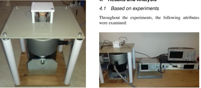
Figure 2:The assembled system
Figure 3:Optimum layout of the magnets
Figure 4:Schematic structure of the loop test
3. Structure of the loop test
The equipment for the loop test was provided by the In- stitute of Mechatronics Engineering and Research of the University of Pannonia in Zalaegerszeg. The schematic structure of the loop test is shown inFig. 4.
Energy harvesting was executed by a type of Lab- works ET-139 electrodynamic shaker. The induced volt- age was displayed by an Agilent DSO5054A digital os- cilloscope. The examined parameters were changed by a function generator, which was connected to a Labworks PA-138 amplifier on a vibration table as illustrated inFig.
5.
4. Results and Analysis 4.1 Based on experiments
Throughout the experiments, the following attributes were examined:
Figure 5:The set-up of the loop test
• Maximum induced voltage without load
• Power without load
• Load on the power
• The impact of the number of coils on the induced voltage and power
The examined energy-harvesting circuit diagram is shown inFig. 6. The structure consists of an internal re- sistanceRband an external resistanceRt(load).
Ptotal= Uind2 Rtotal
= Uind2 Rb+Rt
(1)
Um=Uind Rt Rt+Rb
(2) As a result of the impulsive frequency and amplitude of impulses, electrical energy was induced. The induced voltage was equal to the measured voltage in the absence of external resistance. Measured and induced voltages differed when the system was subjected to an external re- sistance. The relationship between them is described in Eq. 2. The maximum power can be determined fromEq.
1.
4.2 Results
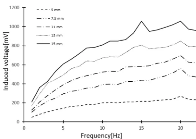
Initially, the device was tested with100turns of the coil.
The internal resistance of the coil was 3.1 Ω. The im- pulsive frequency was set between1and20Hz and the amplitude of impulses between2.5 and15mm. During
Figure 7:Induced voltage by applying100turns of the coil in the absence of external resistance
Figure 8:Induced voltage by applying100turns of the coil in the presence of an external resistance
the experiment, a decrease in the induced voltage was observed above20Hz. Thus, the investigated bandwidth was maximized at20Hz, whereas the trend was still vis- ible in terms of the change in the curves, so20measure- ment points were examined during the experiments.
The results are summarized inFig. 7. The maximum induced voltage and power were986 mV and322mW, respectively.
During the experiments below, an internal resistance equal to the external resistance was applied to the struc- ture. The applied external resistance was3.4 Ω. The re- sults are summarized inFig. 8.
The maximum voltage measured was520mV. Given the values of the external and internal resistances, the in- duced voltage was994mV based onEq. 2. The maximum power was calculated to be152mW fromEq. 1.
The impact of the external resistance on the power During the experiment, a constant excitation amplitude of15mm was applied, while the impact of the resistance on the power was examined. The resistances applied were 1,3.4,10,22,47and74 Ω. The relationship between the changes in resistance and power are summarized inFig.
9.
As is shown in Fig. 9, an exponential decrease in power was observed as the resistance increased. Based on previous studies, an external resistance that is smaller
Figure 9: The relationship between the resistance and power
Figure 10:Induced voltage by applying240turns of the coil in the absence of an external resistance
than the internal resistance is impractical. Ideally, the ex- ternal resistance would be equal to the internal resistance of the coil.
Next, the number of turns of the coil was increased from100to240. The other aforementioned variables re- mained unchanged. The results are summarized inFig.
10.
As shown inFig. 11, the maximum induced voltage without a load and the maximum power were2020mV and559mW, respectively. Following the aforementioned procedures, the loaded system was analyzed.
The external resistance applied was8 Ω. The maxi- mum voltage measured was1060mV. By taking into ac- count the values of the external and internal resistances, the induced voltage was2020mV based onEq. 2. Based onEq. 1, the maximum power calculated was 268mW.
Both the induced voltage and power of the system were doubled by increasing the number of turns of the coil by60%, the induced voltage increased from994mV to 2020mV and the maximum power rose from152mW to 268mW to be exact.
5. Discussion
The aim of the research was based on the principles of linear generator construction and manufacturing. At this stage of the process, it was important that the structure was free of mechanical damping. During the experiment, the structure was examined by means of changing the load resistance and number of turns of the coil in addition to the specified amplitude and frequency. An exponential decrease in the efficiency was observed as the resistance increased. Ideally, the external resistance would be equal to the internal resistance of the coil. The induced voltage and the power of the system were doubled by increasing the number of turns of the coil by60%. As a result, by increasing the number of turns of the coil by60%, the efficiency of the system also increased by approximately 57%. However, a deeper understanding of the relation- ship between the efficiency of the structure and variables
Figure 11:Induced voltage by applying240turns of the coil in the presence of an external resistance
requires further investigation. After doubling the number of turns of the coil, the maximum power generated was 1 W. One advantage of this system in particular is that the neodymium magnets are cheap to produce. Applying a series connection to this system results in a sufficient degree of efficiency to operate the electronic devices in cars.
6. Conclusion
In the aforementioned experiments, the maximum in- duced voltage and power achieved by applying240turns of the coil were2020mV and559mW, respectively. Dur- ing the experiments in the presence of a load resistance, the best value of the power was calculated when the ex- ternal resistance was equal to the internal resistance of the coil. The efficiency of this energy harvesting system can be further enhanced by increasing the number of turns of the coil and the strength of the neodymium magnet.
Symbols
Uind induced voltage Um measured voltage Ptotal power
Rb internal resistance Rt external resistance
Acknowledgements
The project was supported by the European Union and co-financed by the European Social Fund through the project EFOP-3.6.2-16-2017-00002.
REFERENCES
[1] Elmes, J.; Gaydarzhiev, V.; Mensah, A.; Rustom, K.; Shen, J.; Batarseh, I.: Maximum Energy Har- vesting Control for Oscillating Energy Harvesting Systems, 2007 IEEE Power Electronics Specialists Conference, 2007DOI: 10.1109/pesc.2007.4342461
coupled to interface circuits, IEEE T. Circuits-I, 2012,59(12), 3098–3111DOI: 10.1109/tcsi.2012.2206432
[5] Kiziroglou, M.E.; He, C.; Yeatman, E.M.: Electro- static energy harvester with external proof mass, Proceedings of PowerMEMS, 2007, 117–120 [6] Marzencki, M.; Basrour, S.; Charlot, B.;
Spirkovich, S.; Clin, M.: AMEMS piezoelectric vibration energy harvesting device,Proceedings of PowerMEMS, 2005, 45–48
[7] Isarakorn, D.; Briand, D.; Janphuang, P.; Sambri, A.; Gariglio, S.; Tricone, J. M.; Guy, F.; Reiner, J.
W.; Ahn, C.H.; de Rooij, N. F.: Energy harvesting
tion, J. Sound Vib., 2015, 349, 389–402 DOI:
10.1016/j.jsv.2015.03.048
[10] Móricz, L.; Szalai, I.: Mágneses lebegtetés elvén m˝uköd˝o vibrációs energiaátalakító tervezése és építése, (OGÉT 2019 XXVII. Nemzetközi Gépészeti Konferencia, Nagyvárad, Románia), 2019, 352–355
[11] Ashraf, K.; Md Khir, M.H.; Dennis, J.O.; Ba- harudin, Z.: Improved energy harvesting from low frequency vibrations by resonance amplification at multiple frequencies,Sensor Actuat. A-Phys., 2013, 195, 123–132DOI: 10.1016/j.sna.2013.03.026