S I X T H S Y M P O S I U M O N B A L L I S T I C M I S S I L E A N D A E R O S P A C E T E C H N O L O G Y
C O M P A R I S O N O F H I G H - A L T I T U D E S I M U L A T O R S FOR R O C K E T T E S T I N G
V . Ilsen Liquid Rocket Plant A e r o j e t - G e n e r a l Corporation
Sacramento, California
The simulation of high altitude around large nozzles is necessary to provide valid tests for rocket engines. T h e r e fore, the high-altitude simulator has become standard equipment of modern rocket test facilities.
Many agencies have spent considerable effort in the design and investigation of large diffuser s for the above- mentioned purpose. Reports have been published about different ejector shapes that create near-vacuum conditions around the rocket engine during test firing. It has been said that the second-throat type diffuser should give the best r e sults; however, this type diffuser has several limitations, especially for large rocket engines:
1. The configuration of the diffuser preceding the second throat has a profound effect on its performance, especially during startup, which means that for each type of rocket (when the exit diameter, exit angle, a r e a ratio, or gas composition is changed) the configuration must be changed.
2. The position of the second throat and its diameter are evaluated by simple theory (one-dimensional expansion), when in reality the conditions of flow are neither is entropie nor one-dimensional. The results of this type of calculation cannot satisfy the real conditions.
3. The shapes of a diffuser containing conical sections and tubes of different diameter are very complicated and in the case of large rockets, expensive; therefore, the only practical solution is to use a constant-area-duct type diffuser.
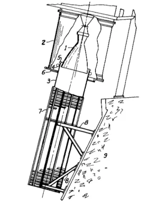
Such a diffuser (Fig 1) having an internal diameter of 5 2 in.
and a length of 216 in. works very well with nozzles having an area ratio £*= 25. The cylindrical duct consists of 330 tubes for water cooling (Ref 1).
During firing, pressures between 1 and 2 psia were observed in the tank surrounding the rocket engine. This
Figure 1. Schematic of water-cooled ejector tube in Aerojet- General test area.
S I X T H S Y M P O S I U M O N B A L L I S T I C M I S S I L E A N D A E R O S P A C E T E C H N O L O G Y
pressure corresponds to an altitude of approximately 60,000 ft.
The straight water-cooled ejector tube has the following useful properties: ( 1) It gives sufficiently low pressures for testing new types of nozzle skirts, (2) The low pressure in the vacuum tank is achieved by relatively simple means, and (3) It is very reliable and produces a stable vacuum during long tests.
Several groups of experiments were conducted at the A e r o j e t - G e n e r a l Corporation in Sacramento with various possible types of straight ejectors.
Two small, bell-shaped nozzles were built for cold flow tests (Fig 2). The nozzles had expansion ratios € = 25 and 45. The exit diameter of the nozzles was approximately 10in.
Internal diameters of the ejector tubes w e r e 12 and 13.5 in.
Different length-to-diameter ratios of ejector tube w e r e tested. Twenty-five different ratios f r o m α = ^ = 0.5 to almost 6.0 w e r e used.
The following variations of ejector tube w e r e tested:
A straight tube.
A tube with a conical ring around the end of the nozzle.
A tube with additional nozzles around the test nozzle.
A tube with an annular nozzle around the test nozzle.
A tube with an elbow near the end.
A straight tube with a deflector plate downstream of the tube.
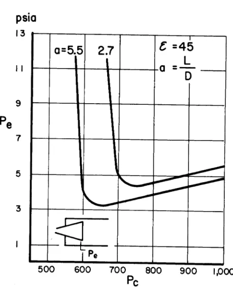
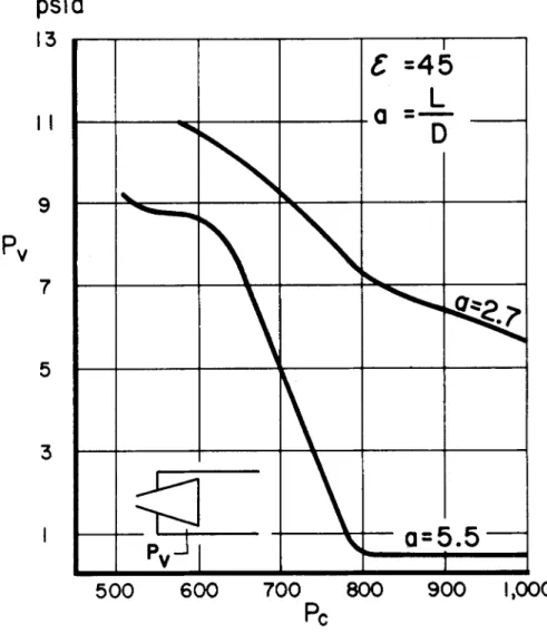
Typical performance curves for the straight ejector tube are presented in Fig 3, 4, and 5. In the lower left corner of each figure is shown a sketch of the nozzle inside the tube.
Many measurements of pressure w e r e made during each test along the tube and along the nozzle. Only two of therri are presented in the diagram: Pe - exit pressure of the noz
zle and Pv - pressure around the nozzle in the vacuum tank.
Fig 3 shows the changes of the exit p r e s s u r e Pe only, and Fig 4 presents only the changes of the tank p r e s s u r e Pv.
Fig 5, shows both the changes in Pe and Pv as functions of chamber pressure Pc for values of α = f between 2. 7 and 5.5. The exit pressure Pe of the nozzle in the tube with a = 5.5 had its lowest value (about 3. 2 psia) at Pc = 650. In another experiment with a = 2. 7 the lowest exit p r e s s u r e was Pe = 4. 1 psia at Pc = 740. With a further rise of the chamber pressure Pc, the exit p r e s s u r e of the nozzle Pe rose almost proportionally, along a straight line.
The pressure around the nozzle fell rapidly to Pv = 0 . 5
S I X T H S Y M P O S I U M O N B A L L I S T I C M I S S I L E A N D A E R O S P A C E T E C H N O L O G Y
Figure 3. Exit pressure Pe in a e = 45 nozzle as a function of chamber pressure Pc. Two lengths of the ejector tube α = 5. 5 and 2. 7.
Figure 4. Tank pressure Ργ around a € = 45 nozzle as a function of chamber pressure Ρ . Two lengths of the ejector tube α = 5. 5 and α = 2. 7.
S I X T H S Y M P O S I U M O N B A L L I S T I C M I S S I L E A N D A E R O S P A C E T E C H N O L O G Y
Figure 5. Diagrams of Figures 3 and 4 combined. Exit pressure Pe and tank pressure Pv in straight ejector tubes of different length.
A r e a ratio of the nozzle e = 45.
Relative tube length α = 5. 5 and 2. 7.
(a = 2. 7) produced only Py = 7 at Pc = 800 and Pv fell further down to 5.1 at Pc = 1, 000 psia.
During the hot tests the pressure P v was considerably lower.
A group of experiments were performed using an addi
tional conical surface around the exit edge of the nozzle. A ring with the conical surface (as shown in F i g 6) was in
stalled inside the ejector tube. The results of several exper
iments are shown in Fig 7. The exit pressure Pe at the exit edge of the nozzle changed almost in the same manner as in the ejector without the ring ( F i g 5). However, the changes in the pressure Pv around the nozzle showed improvement at lower Pc.
In the next large group of experiments, a number of secondary nozzles w e r e used around the main nozzle to in
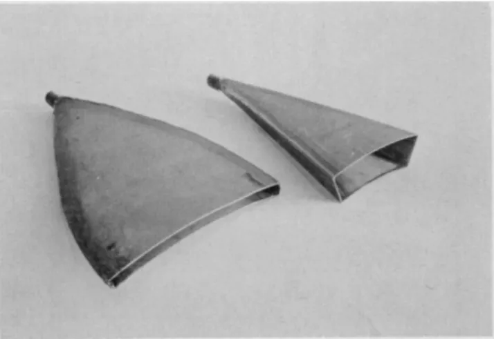
vestigate the effect of additional blowing. Fig 2, shows the nozzles of area ratios £ = 25 and ζ = 45 installed in the ejector tube of the same diameter as in previous tests. The secondary nozzles can also be seen. They had a rectangular cross-section (Fig 8) with the area ratio larger than Ç = 45.
The number of nozzles used was 6 and 8. It was possible to move these nozzles back and forth, thus the exit edge of the auxiliary nozzles could be placed downstream or upstream of the edge of the main nozzle.
The flow rate of all auxiliary nozzles was about 10% that of the main nozzle, when they were connected to the same pressure chamber. In other experiments the driving p r e s sure of the auxiliary nozzles remained the same (1,000 psi) throughout and was independent of the chamber pressure of the main nozzle, which changed in all experiments from 0 to
1.000 psi.
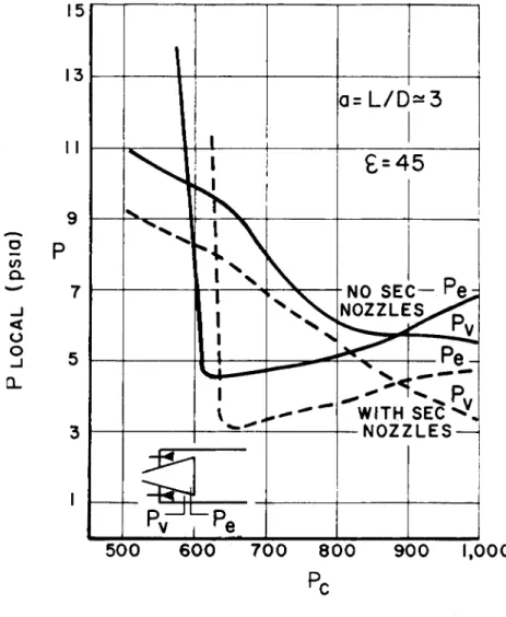
The main character of the phenomena in the case of the ejector with the secondary nozzles is shown in Fig 9. Here the smooth lines present the changes of Pv and Pe without the secondary flow and the dotted lines with the secondary flow.
In these experiments the length-over-diameter ratio was f r o m 3.1 to 2.9. Fig 9 shows that the secondary flow can lower the exit p r e s s u r e , i . e . , make the nozzle flow full. The ejector with secondary flow having the length of 3 DQ p r o duces the same Pe as the ejector without secondary flow having a length of 5. 5 DQ, where DQ is the internal diameter of the ejectors.
The results of the tests with the nozzle having a r e a r a t i o f = 25 a r e shown in Fig 10. Here the range of the in
jector length was from 0. 5 DQ to 3. 5 DQ.
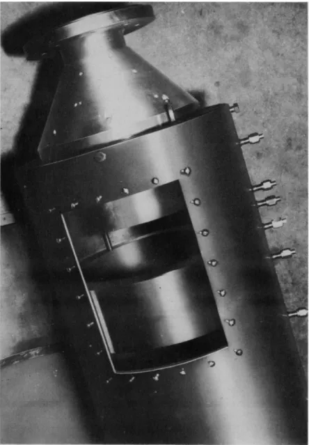
Fig 11 presents the installation of eight secondary noz
zles in an ejector tube around the main nozzle. In Fig 12 the same ejector tube is shown. A group of secondary nozzles can be seen through the open door.
S I X T H S Y M P O S I U M O N B A L L I S T I C M I S S I L E A N D A E R O S P A C E T E C H N O L O G Y
Figure 6. Ejector tube with the conical ring.
Figure 7. Ejector tube with a conical ring around the nozzle exit. Performance of the ejector tubes with relative length α = 2. 2 and 4. 9.
Pe - exit pressure of the nozzle Pv - tank pressure
Nozzle area ratio e = 45.
S I X T H S Y M P O S I U M O N B A L L I S T I C M I S S I L E A N D A E R O S P A C E T E C H N O L O G Y
Figure 8. Secondary nozzles of different types.
15
Figure 9. Ejector tube with a nozzle surrounded by 6 auxil
iary nozzles producing high speed flow around the main nozzle.
A r e a ratio of the main nozzle € = 45 A r e a ratio of the secondary nozzle € = 50 Relative length of the ejector tube α = 3
Full l i n e s - Pe and Pv without secondary injection Dotted l i n e s - Pe and Pv with secondary injection.
S I X T H S Y M P O S I U M O N B A L L I S T I C M I S S I L E A N D A E R O S P A C E T E C H N O L O G Y
500 600 900 1,000
Figure 10. Ejector tube with a nozzle surrounded by 8 auxiliary nozzles.
A r e a ratio of the nozzle e = 25 Relative length of the ejector tube α = 3. 5 and 0. 5.
S I X T H S Y M P O S I U M O N B A L L I S T I C M I S S I L E A N D A E R O S P A C E T E C H N O L O G Y
The use of secondary nozzles, in the opinion of the author, will allow the use of shorter ejectors with consider
ably increased reliability in comparison with ejectors having a second throat, in the tube downstream of the nozzle. This last type of ejector can not be recognized as practical, b e cause it is impossible to predict the contraction and position of the second throat and there are no means to make changes if the ejector will not work properly. However, the situation can be improved by using a simple method of installation of a second throat in a straight ejector tube, shown in Fig 14.
Many segmented inserts made of steel strips, can be in
stalled inside the cylindrical tube. Cooling will be accom
plished by sprinkling water inside the tube around the strips.
The laminas are bent from a straight strip and are much cheaper than the usual conical sections. This design p r e sents a simple solution for adjustment of the diameter and the position of the second throat.
Two very short ejectors with additional flow around the exit edge of the nozzle were built. Both these devices w e r e of very short length and had a length-to-diameter ratio of about 0.4.
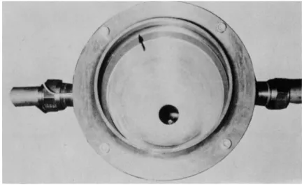
One was used for cold flow tests of a small ( = 45) a r e a ratio nozzle. It consisted (Fig 13) of a manifold with an annular slot (as shown by the a r r o w ) . This slot creates a supersonic stream (of ξ = 46) around the main jet and p r e vents its under expansion. The secondary flow was equal to
10% of the main flow.
The other device, based on the same general idea, had a 50-in. diameter and has been used for hot tests (Fig 15). It had the length-to-diameter ratio of 0.4. The b a r r e l of the shroud was not rigidly connected with the main nozzle and the problem arose of sealing the circular slot between the nozzle and the shroud. Many methods of sealing w e r e tested*
but the pressure around the nozzle was not lower than 7 psia.
The secondary flow was about 2% of the main flow.
Other methods of building very short ejectors a r e now under investigation.
Several experiments were made with the ejector tube having an elbow with a 40° angle. In one group of experi
ments the cross section of the tube after turning was round, in another group the downstream portion was square. The performance diagram and a sketch of installation are shown in Fig 16.
The effect of various positions of a deflector plate at the end of the straight ejector tube was also investigated. Both
Figure 12. Ejector tube with the secondary nozzles around the main nozzle. Cold flow tests.
Figure 13. Shroud around the nozzle exit. Annular slot produces high speed supersonic flow around the main jet.
S I X T H S Y M P O S I U M O N B A L L I S T I C M I S S I L E A N D A E R O S P A C E T E C H N O L O G Y
Figure 15. Short ejector tube for full-scale hot firing.
Many secondary nozzles around it.
S I X T H S Y M P O S I U M O N B A L L I S T I C M I S S I L E A N D A E R O S P A C E T E C H N O L O G Y
Figure 16. Performance of the ejector tube with 40° elbow.
C onclusion
Three types of ejectors with additional flow around the nozzle were tested and showed improved performance.
Additional investigations will continue.
A straight ejector tube can produce satisfactory condi
tions around the nozzle. The simplicity and low cost of design make this type of ejector attractive. A straight ejector with an elbow or with a deflector plate at the end also can be used if there is limited available space.
References
1. Ilsen, V., "A Large Rocket Ejector System, 11 P r o g r e s s in Astronautics and Rocketry, Vol. 2, ARS Series, i960.
2. Ilsen, V . , Experimental Simulation of High Altitude by Cylindrical Ejector System, Aerojet Report T C R 185,
τ^π.
3. Hagginbotham, V . , Straight Pipe Diffuser Thrust Stand, etc. , 7th Annual A r m y - N a v y - A i r Force Meeting,
Sacramento, 1958.
4. M a s s i e r , P. , et al. "Experimental Investigation of Exhaust Diffusers for Rocket Engines," P r o g r e s s in Astronautics and Rocketry, Vol. 2, I960"
5. Holzman, A . , et al. "Summary of Experience in the Use of Exhaust Diffusers for Rocket Testing," P r o g r e s s in Astronautics and Rocketry, Vol. 2, I960.
6. Rao, G. , "Short Diffuser for Testing Rocket Nozzles,"
P r o g r e s s in Astronautics and Rocketry, Vol. 2, I960.
7. Chamberlain, J. , et al. "Development of an Exhaust Diffuser for Ground Testing Rocket Engines," P r o g r e s s in Astronautics and Rocketry, Vol. 2, i960.
