External Rapid Prototyping Validation System for the Automotive Development Cycle
Ioan Gheorghe Dubar
1, Razvan Bogdan
2, Mircea Popa
21FEV ECE Automotive, Neuenhofstraße 181, 52079 Aachen, Germany, dubar_i@fev.com
2Politehnica University of Timisoara, Faculty of Automation and Computers, No.
2, blv. Vasile Pârvan, RO-300223 Timişoara, România, razvan.bogdan@upt.ro, mircea.popa@upt.ro
Abstract: The most pressing requirement currently faced by the automotive industry is the speed at which a certain product can be offered to the market. The present paper discusses the applicability of the Rapid Prototyping method in the automotive industry, illustrated as a development approach of a potential solution to the early evaluation phase of a system.
The offered method advances an implementation of a pilot approach in the context of the final product. The functioning of the prototype is measured in different test scenarios, the results being increasingly encouraging towards the industrial adoption of this technique from a technical as well as an economic point of view.
Keywords: Automotive; Engine Control Unit; External Rapid Prototyping; Performance
1 Introduction
The automotive industry is among the leading divisions of the currently-emerging economy. Different corporations have been created with the aim of meeting the complex requirements of a large spectrum of customers. A plethora of technologies, open problems as well as products are living proof that this field is one of the most dynamic industrial domains. Different customers from all the continents offer large amounts of money so that competitive products can be launched on the market. The key ingredient of such an industry has become the speed at which a corporation offers a certain product to the market. Different techniques, processes and methodologies are being researched and tested so that the life cycle of a product is shortened as much as possible.
In order to face such a situation, in which automotive control systems are more and more complex and the economic factor is an impactful constraint in developing a final product, the great urge of testing and validating new concepts
during the development process has led towards new prototypes [1]. These are executable models of a system that accurately reflect a chosen subset of its properties. In other words, one of the solutions to such a problem is to create a system that allows to develop and test new implemented requirements and concepts that are aimed at being included in the final automotive product. To obtain these prototypes, one of the methods that could be applied at the software and hardware level is the Rapid Prototyping method. This paper presents such a solution that could be successfully applied in the automotive industry.
The Rapid Prototyping method can be applied in two different approaches, the External Rapid Prototyping (eRPT) and the Internal Rapid Prototyping (iRPT).
The External Rapid Prototyping does not affect the processing capabilities of the Electronic Control Unit (ECU). All the processing resources that must be available for eRPT implementation are ensured by an external Rapid Prototyping Unit (RPU). There is also a second version of Rapid Prototyping, which is an alternative to External Rapid Prototyping and is called Internal Rapid Prototyping (iRPT) [2]. These two methods of Rapid Prototyping have basically the same principles, however they differ at the implementation level. The SDA-iRPT (System Design Automation) uses free resources of the running ECU and can be implemented only if the ECU has enough unused memory space for the model code, the model RAM and the model calibration data in the ECU memory.
Furthermore, enough free processor runtime is needed to run the bypass-model.
To have a better overview of the system, it should be mentioned that the experimental setup of our approach is a serial production ECU that can be found on Ford C-MAX cars. This ECU is equipped with a MPC561 microcontroller, provided by Freescale. This microcontroller provides only 32-kbytes static RAM and 40 Mhz processing frequency. Due to these limited resources, the chosen method for applying Rapid Prototyping is the External Rapid Prototyping (eRPT) method. In order to be able to apply such a method, external data processing power will be applied and the validation will be performed by means of a new injectors control algorithm. The external processing unit and the hardware interface that makes possible the communication with the ECU are provided by dSPACE as well as the entire tool chain, from control tools for experiments to specific eRPT libraries for Matlab Simulink for the experimental models.
The content of the paper is structured in four main sections as follows: the first reviews previous cases where Rapid Prototyping has been successfully applied;
the second describes the proposed solution aimed at system overview, hardware and software implementation and the adaptation of the model for External Rapid Prototyping; the third section discusses the results achieved, whereas the last section formulates conclusions and future research directions.
2 Related Work
Rapid prototyping methods are present in many branches of the industry, especially in those where the development phases are expensive and time consuming. According to the already published state-of-the-art scientific literature, this method has not been previously applied in the area of Electronic Control Units. Therefore, this section of the paper will have two distinct directions: it will present those automotive areas where the applicability of this technique has been researched and different results are available, and then other industrial domains which have successfully benefitted from this method will be presented.
Rapid prototyping has been successfully applied in different fields of the automotive industry. In [2], two approaches are presented. First, a methodology and integrated tool set for rapid prototyping of communication systems is discussed which uses programmable boards from high-level requirements. The prototype for the system is obtained via synthesis. Secondly, a Virtual Component CO-Design (VCC) environment is used to model the distributed system being composed of Electronic Control Units (ECUs), different functions and communication protocols. Even if this solution supports two methodologies, namely virtual rapid prototyping of communication protocols and virtual and physical prototyping of applications, only preliminary results have been obtained so far. In [3] the case of applying the rapid prototyping approach to design and test active vibration control systems is presented. This solution uses the dSPACEMicroAutoBox rapid prototyping systems, with the support of tools such as MATLAB/Simulink/Stateflow. By using such a method, it has been successfully proven that important reductions in noise and vibrations can be achieved. In [4] a case study of rapid prototyping from the automotive industry is presented, namely the identification of usability problems at the beginning of the software life cycle. This paper aims at offering some results on the effectiveness and performance of prototypes in usability scenarios. In [5] a Real-Time model that substitutes a real DC motor is presented for designing a cost effective Power- Hardware-In-the-Loop. The rapid prototyping method is used in order to simulate behavior characteristic of the real DC motor.
In additon to the automotive industry, rapid prototyping has been used in the case of robot manipulators as well [6]. Force sensors are also used in robotic systems, providing critical information about the robot manipulators. The main downsides of force sensors are excess sizes, cost and fragility. In order to improve these aspects, 3-D printing is used for obtaining a quick and inexpensive development process. The big advantage of rapid prototyping, combined with 3-D printing, is that a final product is developed and built faster, it is easy to customize it and can be shared with other developers in the field in an open source approach. Other application domains of rapid prototyping method are wireless sensor networks,
internet of things, FPGAs [7-16], as well as medicine [17, 18], robotic systems [19] and power electronics [20].
3 Proposed Solution
The solution advanced by this paper is based on the implementation of the External Rapid Prototyping method in order to address the above mentioned shortcomings within the automotive industry. An automotive hardware/software system which allows the practical implementation of the External Rapid Prototyping has been implemented and the performance of the obtained system has been measured, as well as the gain in terms of V-cycle development process.
The motivation for applying this method is to obtain an improved performance of control algorithms for injectors, through, which is made the fuel injection in a thermal motor. Moreover, an important aspect is the fact that the system is based on a serial production Engine Control Unit (ECU SID 803), found on mass production cars. The following steps are proposed to be followed in order to obtain the solution:
a. Hardware implementation of the system
b. Mathematical model Matlab\Simulink for Rapid Prototyping c. Software implementation
d. Performance analysis of the entire system.
The concept of External Rapid Prototyping is quite new in the automotive field and the word “external”, placed before Rapid Prototyping, means that the processing data capabilities for automated code generation from an improved model of the target system and the execution of this code are ensured by external hardware. In this way, the impact on the computing resources of the engine control unit is smaller.
The following subsections will present an overview of the system and all the stages of the implementation, hardware, software and model adaptation.
3.1 System Overview
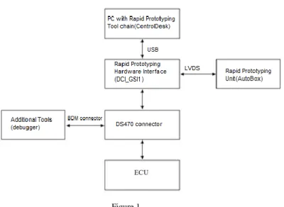
A system overview from the hardware viewpoint of the proposed solution is presented in Figure 1.
Figure 1 Hardware overview
The main device of our solution is the ECU (Electronic Control Unit) of the car.
The ECU SID 803 is used, that is found on the Ford C-Max (Engine: Duratorque 2.0L, DW10B, Power: 136HP, Injection: Common Rail Piezo, Transmission:
Manual 6 gears) and it is equipped with the MPC561 micro-controller.
The DCI_GSI_CON1 (DS470) is a NEXUS/READI connector adapter for the MPC561 microcontroller which makes possible the communication between the ECU and the Rapid Prototyping Unit. So as not to alter the functionality of the whole circuit and in order to have both devices functional, i.e. the debugger (Trace32) and the DCI_GSI1 (Generic Serial Interface), a hardware wiring of the mapping was made directly between the corresponding debugger adaptor pins and the DCI_GSI_CON1 pins. In this way, the native debug interface remains functional.
Many microcontrollers used in the automotive ECUs today provide internal units, for example overlay RAM for supporting ECU calibration, measurement or debugging. These internal units can be accessed by a chip interface such as a debug interface or any other serial interface which allows memory read/write access by an appropriate protocol (for example, NBD/AUD or Nexus). The DCI- GSI1 uses this interface to access the internal units to perform ECU calibration, measurement and bypassing. The DCI_GSI1 uses the NEXUS/READI interface to facilitate the communication between ECU and AutoBox.
The Rapid Prototyping Unit for our solution is the Autobox. This hardware is provided by dSPACE and has several features that make it suitable for eRPT.
Among them one can mention AutoBoot options for making stand-alone operations, existence of several hardware interfaces for connection and communication with a host PC or supply voltage from a car battery. Usage of
Autobox is well suited to experiments performed directly on real-time systems inside a car. It is equipped with a rugged case, inside of which one can mount up to six boards, processing data collected from the system, or even interfacing with other equipment boards.
By means of a host PC/Laptop we can control the whole development process, for example collecting useful data from the ECU or making the desired adaptation on the ECU code. For this, the PC must be equipped with a certain tool chain that consists of:
a. SDA-Matlab/Simulink with RPT configuration –SDA (System Design Automation) is a Matlab/Simulink base tool;
b. ControlDesk - a software tool for controlling, monitoring and automation experiments using dSPACE hardware;
c. INCA - a tool that allows, based on a .a2l file, the monitoring of all variables contained in the code flashed on the ECU.
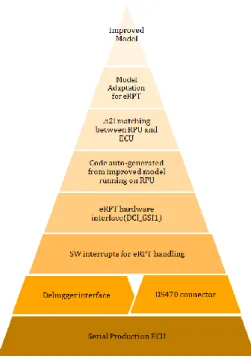
On the other hand, from an architectural viewpoint, the system is structured as presented in Figure 2. This illustrates the dependencies between different levels of the whole system.
Figure 2 System architecture
At the bottom of the pyramid is placed the ECU and after that the DS470 connection tower and debugger connector. These two devices are placed on the same level because through them the ECU communicates with the superior layers.
Through the debugger interface, the software suitable for Rapid Prototyping can be flashed on the ECU. By having this layer available, through the Rapid Prototyping hardware interface, the communication with the RPU (Rapid Prototyping Unit) is ensured. On this unit, the code is generated from a prototype model, which can be improved for a certain functionality.
The last three levels of the pyramid show the link between the improved model and the RPU, through a model adaptation in the input signals part of the model, where all the input and output signals of the model are present and a couple of .a2l files that make the address matching of the variables from ECU and RPU.
In terms of system implementation, the activities could be grouped into three major parts: hardware, software and prototype model adaptation implementation.
3.2 Hardware Implementation
In order to have the hardware implementation, it is necessary to adapt a serial engine control unit, having the role to communicate with the external rapid prototyping unit, AutoBox, through a hardware interface, DCI_GSI1 (Figure 3).
These are both delivered by dSPACE. This is possible through a third-party connector tower, DS470, for the MPC561 microcontroller of the engine control unit.
Figure 3
Data flow: from the Matlab/Simulink improved model, up to physical output
Nevertheless, an important problem remains. By using simultaneously the debugger hardware interface and DCI_GSI1, in order to flash code on the ECU, serious damage might be caused to the devices. This problem is present due to the fact that the DS470 connector has also dedicated pins for the debug interface of
the microcontroller and they are included in the auxiliary NEXUS port for communication with DCI_GSI1.
To solve this issue, a mapping of the associated pins of BDM debugger connector signals, debugging pins of the microcontroller and DS470 pins is required. The required mapping between the three hardware components is presented in Table 1.
Table 1
Required mapping between hardware components BDM
Connector Pin
BDM Signal DS470 Pin DS470 Signal
8 DSDI 15 MDI0
4 DSCK 17 MCKI
10 DSDO 19 MDO0
1 VFLSO 25 MSEO0
9 VREF 8 VREF
After a hard wired connection of the mapping described in the table above, both communication of the microcontroller with the DCI_GSI1 and the debug interface, were functional. A physical limitation is that it is not recommended to use both debug interface and DCI_GSI1 interface simultaneously because electrical problems could appear.
3.3 Software Implementation
In order to make the system compatible for external Rapid Prototyping, a simple software re-flash is not enough. Therefore, an interrupt mechanism which activates the External Rapid Prototyping unit, AutoBox, during each 10 ms recurrence, is triggered by adding the code presented in Figure 5. This must be done because on the AutoBox the code generated from the improved model will run and at each 10 ms new values of the targeted variables are delivered. These values are different from the ones delivered by the software flashed on the engine control unit. The interrupt mechanism is presented in Figure 4.
Also, at this level, after compiling the whole serial production project with the modifications mentioned above, an .a2l file is generated. This file is important because it also contains the memory mapping of all variables present in the software.
Figure 4 The interrupt mechanism
3.4 Prototype Model Adaptation for External Rapid Prototyping
In order to make a better overview of the serial production software that is flashed on the engine control unit, this is divided into smaller modules. Each software module is developed based on a model developed in a plug-in tool, based on Matlab/Simulink. Each module of the software can be either manually coded or auto generated and introduced in the whole project.
A specific module that contains a control algorithm of the injection has been chosen and the according model adapted for External Rapid Prototyping. For this, in the model, there is a special section, Stimuli, where this adaptation is made. It contains dedicated blocks for mapping the memory addresses of the targeted variables between the engine control unit and the Rapid Prototyping unit.
Read blocks are dedicated blocks for model communication with DCI_GSI1.
Those can be found in the Simulink library, at section
“dSPACERTIBypassBlockset”, named “RTIBYPASS_READ_BLx” (Figure 5).
In the model created for the application, several blocks of this type were introduced because each block can handle a maximum of ten variables.
Figure 5
Read blocks for targeted variables
This is made through a couple of .a2l files. The first one is the .a2l file generated after building the project, as it was mentioned in the previous section. The second one is an .a2l file, used internally by the Rapid Prototyping Unit, which contains the addresses of the targeted variables from its own environment. By its own environment, the memory mapping of the microcontroller from the development boards can be understood, on which, runs the code generated from the improved model.
At run-time it is ensured that selected variables from the prototype model can be read, and even more, the new calculated values overwritten in real-time on the engine control unit, at the corresponding addresses, without being necessary to make a re-flash of the whole software. In order for these blocks to have the desired functionality, some specific settings must be made. The first thing to set is the interface used for bypass, in our case GSI. A second .a2l file is used which enables communication between ECU and Autobox through DCI_GSI1. This file basically realizes the communication port mapping, length of the messages exchanged between the equipment and other communication settings.
On the other hand, there are also the RTIBYPASS WRITE BLx blocks. These blocks write variables back to the ECU that are output variables of the calculated bypassed functions on the prototyping system. The variables to be written to the ECU should be selected, and specify the bypass interface and the service instance which should be used for writing the variables. The setup block must be placed within the SDA-eRPT RPT WRITE subsystem. These blocks offer the possibility to select the service instance of the ECU where the block has to write the variables. The names of the service instances are unique, and each service instance corresponds to one service ID. The Service Instance drop-down list contains the available service instances, determined by the selected imported database files (bypass .a2l file) for the selected bypass interface.
4 Results
The results of the proposed solution can be quantified in two directions. The main line of the study has been to understand how the new system affects the load on the microprocessor of the engine control unit. The second line was the economic one, more precisely which steps of the V cycle development process are eliminated by implementing the proposed method. For the first direction, five test cases were designed. For test case 0 an arbitrary number of variables to be read were chosen from the prototype system and decrease them sequentially up to test case 4. Figure 6 illustrates the results, more precisely, how the CPU load varies depending on the number of variables that are read and the engine speed. A maximum number of 76 signals were monitored. This is the exact number of input and output signals of the module that was chosen to be improved.
Figure 6
CPU load as a function of engine speed
One can notice the decrease of CPUload from one case to another, with the biggest load when the system reads 76 variables, and less charging in the final case. Aditionally, it can be remarked that the variation is about 0.4% CPUload with a change in the speed N of 100 units, during the same measurement, and 0.15-0.2% in a measurement to another for the same values of N. Another criterion was to measure if the time segment, which has a correlation with the engine speed, will be affected by the CPU load increase. This is important because
the relation between the engine speed and the segment time is an inversely proportional one, meaning a higher engine speed, a smaller time segment. All the logic contained by the functions called at segment time must be executed, so a decrease of segment time means an increase of CPU load. Adding the CPU load increase due to Rapid Prototyping system, the segment time could be affected.
Figure 7
Segment time as a function of engine speed (case 1)
Figure 8
Segment time as a function of engine speed (case 2)
Figure 9
Segment time as a function of engine speed (case 3)
Figure 10
Segment time as a function of engine speed (case 4)
Figure 11
Segment time as a function of engine speed (case 5)
It can be noticed (Figure 7 – Figure 11) that the segment time is the same during all five measurements, given the fact that the Rapid Prototyping is negligible, the overall performance of the system is not affected.
On the other hand, the main output from the improved prototyped model is the fuel pressure in the common rail of the thermal motor, PFU. The pressure is obtained based on the value from the previous recurrence and is made at segment recurrence, which may last under 1 ms, at high engine speeds. This implies a signal acquisition at a very high rate. Figure 12 shows that the engine speed gradient is the same for all measurements, but still the amount of acquired data affects the acquisition.
Figure 12
Fuel pressure as a function of engine speed
The first measurement in Figure 12 is quite unstable with high variations of PFU.
In the next measurements, a decrease of the variables that are read through Rapid Prototyping system is operated, the logic of the model being maintained from a measurement to another. The smaller the number of signals acquired from the system, the more accurate the read of the PFU is made. To sum up, it is important to know what meaningful data must be read through the Rapid Prototyping system in order to have accurate data available.
The second direction of the results achieved is aimed at the economic improvement.
Figure 13
Eliminated steps from the developing process
Figure 13 describes a classic V cycle development, which is very common in the automotive field. Through the system that was developed, all the steps that are marked in the red section are mainly removed from the whole process. By this, there is a huge gain in terms of time and costs because the system allows a true validation [21] of the new concepts implemented in the prototype model because of the serial produced ECU, which is the main core piece of the system.
Conclusions
Considering that a classic development cycle on different functionalities from the engine control unit lasts between two and three years, by using the method proposed by this paper, this amount of time can be reduced significantly to only several months.
The novelty of the system produced for this paper is that it is the first time when the eRPT method has been applied on a serial production ECU, not on development or prototype ECUs.
According to the available state-of-the-art scientific literature, different automotive and industrial areas have harnessed this technique, yet it has not been previously applied on serial productions ECUs. The system reproduces 100% the final environment in which the new functionality will run, while the obtained results illustrate how the key parameters of the engine control unit will be affected by the Rapid Prototyping system. By this approach, the hardware validation is removed from the V-cycle, resulting in cost reduction from a time and money perspective. The proposed experiments show how each targeted key parameter have acceptable, even negligible deviations. In this manner a highly accurate validation of the developed prototype models is ensured. Furthermore, the prototypes can be developed in an evolutionary approach and the code corresponding to the final prototype model can be introduced directly in the final software product.
Acknowledgement
The implementation of the system underlying this paper has been facilitated by Continental Automotive Romania, and all the information presented in the paper has the approval of the company to be made public.
References
[1] F. Kordon, “An Introduction to Rapid System Prototyping”, IEEE Transactions on Software Engineering, Vol. 28, Issue 9, 2002, pp. 817-821, DOI: 10.1109/TSE.2002.1033222
[2] B. O'Rourke, P. Giusto, T. Demmeler, S. Wisniewski, “Rapid Prototyping of Automotive Communication Protocols”, in Proc. 12th International Workshop on Rapid System Prototyping, Monterey, USA, 2001, pp. 64-69, DOI: 10.1109/IWRSP.2001.933840
[3] K. Kowalczyk, H. J. Karkosch, P. M. Marienfeld, and F. Svaricek, “Rapid Control Prototyping of Active Vibration Control Systems in Automotive Applications”, in Proc. IEEE Conference on Computer-Aided Control Systems Design, Munich, Germany, 2006, pp. 2677-2682, DOI:
10.1109/CACSD-CCA-ISIC.2006.4777062
[4] A. Holzinger, O. Waclik, F. Kappe, S. Lenhart, G. Orasche, B. Peischl,
“Rapid Prototyping on the Example of Software Development in Automotive Industry: The Importance of their Provision for Software Projects at the Correct Time”, Proc. International Conference on e-Business (ICE-B), Seville, Spain, 2011, pp. 1-5
[5] J. Chalupa, R. Grepl, V. Sova, “Design of Configurable DC Motor Power- Hardware-in-the-Loop Emulator for Electronic-Control-Unit Testing”, Proc. 21st International Conference on Automation and Computing (ICAC), Glasgow, United Kingdom, 2015, pp. 1-6, DOI:
10.1109/IConAC.2015.7313987
[6] Samuel B. Kesner, Robert D. Howe, “Design Principles for Rapid Prototyping Forces Sensors Using 3-D Printing”, IEEE/ASME Transactions on Mechatronics, Vol. 16, Issue 5, 2011, pp. 866-870, DOI:
10.1109/TMECH.2011.2160353
[7] P. L. Evans, A. Castellazzi, C. M. Johnson, “Design Tools for Rapid Multidomain Virtual Prototyping of Power Electronic Systems”, IEEE Transactions On Power Electronics, Vol. 31, No. 3, 2016, pp. 2443-2455, DOI: 10.1109/TPEL.2015.2437793
[8] C. P. Kruger, A. M. Abu-Mahfouz, G. P. Hancke, “Rapid Prototyping of a Wireless Sensor Network Gateway for the Internet of Things Using Off- the-Shelf Components”, Proc. IEEE International Conference on Industrial Technology (ICIT), Seville, Spain, 2015, pp. 1926-1931, DOI:
10.1109/ICIT.2015.7125378
[9] S. Buso, T. Caldognetto, “Rapid Prototyping of Digital Controllers for Microgrid Inverters”, IEEE Journal of Emerging and Selected Topics in Power Electronics, Vol. 3, Issue 2, 2015, pp. 440-450, DOI:
10.1109/JESTPE.2014.2327064
[10] K. Buchenrieder, “Rapid Prototyping of Embedded Hardware/Software Systems”, Design Automation for Embedded Systems, Vol. 5, 2000, pp.
215-221
[11] C. Bieser, K. D. Mueller-Glaser, “Rapid Prototyping Design Acceleration Using a Novel Merging Methodology for Partial Configuration Streams of Xilinx Virtex-II FPGAs”, Proc. 17th IEEE International Workshop on Rapid System Prototyping (RSP), Chania, Crete, 2006, pp. 193-199, DOI:
10.1109/RSP.2006.32
[12] R. Selvamuthukumaran, R. Gupta, “Rapid Prototyping of Power Electronics Converters for Photovoltaic System Application Using Xilinx System Generator”, IET Power Electronics, Vol. 7, Issue 9, 2014, pp. 2269- 2278, DOI: 10.1049/iet-pel.2013.0736
[13] B. D. Rouhani, E. M. Songhori, A. Mirhoseini, F. Koushanfar, “SSketch:
An Automated Framework for Streaming Sketch-based Analysis of Big Data on FPGA”, Proc. IEEE 23rd Annual International Symposium on Field-Programmable Custom Computing Machines (FCCM) 2015, pp. 187- 194, DOI: 10.1109/FCCM.2015.56
[14] S. Gadelovits, M. Sitbon, A. Kuperman, “Rapid Prototyping of a Low-Cost Solar Array Simulator Using an Off-the-Shelf DC Power Supply”, IEEE Transactions on Power Electronics, Vol. 29, Issue 10, 2014, pp. 5278-5284, DOI: 10.1109/TPEL.2013.2291837
[15] A. D. Lantada, V. P. Klaus Plewa, N. Barie, M. Guttmann, M. Wissmann,
“Toward Mass Production of Micro-Texturedmicro-Devices: Linking Rapid Prototyping with Microinjection Molding”, The International Journal
of Advanced Manufacturing Technology, Vol. 76, Issue 5-8, 2015, pp.
1011-1020, http://dx.doi.org/10.1007/s00170-014-6333-2
[16] A.Tisan, J. Chin,“An End-User Platform for FPGA-based Design and Rapid Prototyping of Feedforward Artificial Neural Networks with On- Chip Backpropagation Learning”, IEEE Transactions on Industrial Informatics, Vol. 12, Issue 3, 2016, pp. 1124-1133, DOI:
10.1109/TII.2016.2555936
[17] L. de Melo, M. T. da Silva, J. Martins, D. Newman, “A Microcontroller Platform for the Rapid Prototyping of Functional Electrical Stimulation- based Gait Neuroprostheses”, Artificial Organs, Vol. 39, Issue 5, 2015, pp.
56-66, DOI: 10.1111/aor.12400
[18] A. Taddese, M. Beccani, E. Susilo, P. Volgyesi, A. Ledeczi, P. Valdastri,
“Toward Rapid Prototyping of Miniature Capsule Robots”, Proc. IEEE International Conference on Robotics and Automation (ICRA) 2015, pp.
4704 – 4709, DOI: 10.1109/ICRA.2015.7139852
[19] L. Simoni, M. Beschi, D. Colombo, A. Visioli, R. Adamini,“A Hardware- In-the-Loop Setup for Rapid Control Prototyping of Mechatronic Systems”, in Proc. IEEE 20th Conference on Emerging Technologies & Factory Automation (ETFA) Luxembourg, 2015, pp. 1-4, DOI:
10.1109/ETFA.2015.7301628
[20] H. Vardhan, B. Akin, H. Jin,“A Low-Cost, High-Fidelity Processor-in-the Loop Platform: For Rapid Prototyping of Power Electronics Circuits and Motor Drives”, IEEE Power Electronics Magazine, Vol. 3, Issue: 2, 2016, pp. 18-28, DOI: 10.1109/MPEL.2016.2550239
[21] S. Folea, R. De Keyser, I. R. Birs, C. I. Muresan, C. Ionescu, “Discrete- Time Implementation and Experimental Validation of a Fractional Order PD Controller for Vibration Suppression in Airplane Wings”, Acta Polytehnica Hungarica, Vol. 14, Issue: 1, 2017, pp. 191-206, DOI:
10.12700/APH.14.1.2017.1.13