The Special Characteristics of Stepping Motor Drives and a New Type of Classification
László Számel, Tibor Vajsz
Budapest University of Technology and Economics, Department of Electric Power Engineering, Egry József utca 18, H-1111 Budapest, Hungary E-mail: szamel.laszlo@vet.bme.hu, vajsz.tibor@vet.bme.hu
Abstract: Stepping motor drives are widely used for positioning applications due to their easy controllability and straightforward connectivity to digital electronics. One of their greatest advantages is the possibility to perform positioning without requiring a closed- loop position control system. Stepping motor drives have special characteristics and therefore are considered as special types of electric drives. In this paper, these special characteristics are presented, along with a new type of classification. This classification is based on both the presented special characteristics (construction, etc.) and a newly derived equation called the fundamental equation of stepping motor drives. It is also shown in this paper that based on the new classification stepping motor drives can be divided into two subcategories: synchronous-type and asynchronous-type steppers. These subcategories are based on their similarities to traditional synchronous- and asynchronous (induction) motor drives. Also, the basic equations of the presented stepping motor drives will be derived from the fundamental equation of stepping motor drives. Therefore, this new type of classification is well applicable for both scientific analysis and educational purposes.
Keywords: stepping motor; stepper motor; step motor; special characteristic;
classification; the fundamental equation of stepping motor drives; variable reluctance stepping motor; permanent magnet stepping motor; hybrid stepping motor
1 Introduction
1.1 The Basic Characteristics of Stepping Motor Drives
Stepping motor drives have been a subject of investigation for a long time. This is due to the fact that stepping motor drives have a very wide variety of construction.
They are frequently used in low-power applications. The number of phases is usually two, three, four, or five. The arc of a full step is between 0,72° and 15° in most cases. The number of steps per revolutions for a 0,72° full-step motor in half-stepping mode is 1000, which is in the lower range of the resolution of the digitalized-output incremental encoders. There are three types of stepping motors:
variable reluctance, permanent magnet, and hybrid [1].
The magnetic field established in the stator can be unidirectional or bidirectional, depending on the type of the stepping motor used. In the case of variable reluctance stepping motors the application of unidirectional magnetic field is sufficient, while in the case of permanent magnet stepping motor drives the bidirectional magnetic field can be well-used for increasing the electromagnetic torque of the motor.
All of the stepping motors are used in an open-loop fashion, which means that current-control is independent of the position of the rotor and therefore the electromagnetic torque of the machine is not flat. This results in a reduced loadability. This is similar to the V/F controlled permanent magnet synchronous motor drive, where a load-torque step causes heavy speed-oscillations and therefore the loadability of the drive must be reduced in order to prevent falling out of synchronism.
Nowadays, other solutions are becoming more and more popular, where current- control of a stepping motor depends on the actual position of the rotor. Therefore, the loadability of the motor is improved [2], [3].
1.2 The Fundamental Equation of Stepping Motor Drives
An electric machine produces electromagnetic torque of non-zero mean-value if the stator- and the rotor magnetic fields are at standstill relative to each other [4].
This requirement is often called the speed-requirement or the frequency- requirement and is widely used in Hungary for the classification of conventional electric machines [5]. The speed-requirement can be expressed as follows:
𝜔𝑠𝑡𝑎𝑡𝑜𝑟−𝑓𝑖𝑒𝑙𝑑,𝑠𝑡𝑎𝑡𝑜𝑟= 𝜔𝑟𝑜𝑡𝑜𝑟−𝑓𝑖𝑒𝑙𝑑,𝑟𝑜𝑡𝑜𝑟+ 𝜔𝑟𝑜𝑡𝑜𝑟 (1)
Where:
𝜔𝑠𝑡𝑎𝑡𝑜𝑟−𝑓𝑖𝑒𝑙𝑑,𝑠𝑡𝑎𝑡𝑜𝑟: the angular speed of the stator-field relative to the stator 𝜔𝑟𝑜𝑡𝑜𝑟−𝑓𝑖𝑒𝑙𝑑,𝑟𝑜𝑡𝑜𝑟: the angular speed of the rotor-field relative to the rotor 𝜔𝑟𝑜𝑡𝑜𝑟: the angular speed of the rotor
In the case of synchronous machines the rotor-field is fixed to the rotor and therefore:
𝜔𝑟𝑜𝑡𝑜𝑟−𝑓𝑖𝑒𝑙𝑑,𝑟𝑜𝑡𝑜𝑟= 0
𝜔𝑠𝑡𝑎𝑡𝑜𝑟−𝑓𝑖𝑒𝑙𝑑,𝑠𝑡𝑎𝑡𝑜𝑟= 𝜔𝑟𝑜𝑡𝑜𝑟 (2)
In the case of DC-machines the stator-field is fixed to the stator and therefore:
𝜔𝑠𝑡𝑎𝑡𝑜𝑟−𝑓𝑖𝑒𝑙𝑑,𝑠𝑡𝑎𝑡𝑜𝑟= 0
𝜔𝑟𝑜𝑡𝑜𝑟−𝑓𝑖𝑒𝑙𝑑,𝑟𝑜𝑡𝑜𝑟= −𝜔𝑟𝑜𝑡𝑜𝑟. (3)
In the case of asynchronous (induction) machines, neither is the stator-field fixed to the stator, nor is the rotor-field fixed to the rotor. Therefore, in (1) nothing is necessarily zero, which means that the case of asynchronous machines is the most general among the three basic machine types.
The classification of stepping motor drives is not obvious. This is because in the case of stepping motors each phase conducts occasionally and therefore a movement of the stator- and the rotor magnetic fields occur only when the conducting stator phase is changing. It must be mentioned that stepping motor drives are basically considered synchronous motor drives, because in steady-state the speed of the motor can be controlled by the switching frequency. However, some of the stepping motor drives are supplied by direct currents and this makes their classification difficult. Therefore, stepping motor drives are rather classified as special electric motor drives.
The following equation can be derived from (1) for stepping motor drives:
∆𝛼𝑠𝑡𝑎𝑡𝑜𝑟−𝑓𝑖𝑒𝑙𝑑,𝑠𝑡𝑎𝑡𝑜𝑟= ∆𝛼𝑟𝑜𝑡𝑜𝑟−𝑓𝑖𝑒𝑙𝑑,𝑟𝑜𝑡𝑜𝑟+ ∆𝛼𝑟𝑜𝑡𝑜𝑟 (4) Where:
∆𝛼𝑠𝑡𝑎𝑡𝑜𝑟−𝑓𝑖𝑒𝑙𝑑,𝑠𝑡𝑎𝑡𝑜𝑟: the change in the position of the stator-field relative to the stator for one step-period
∆𝛼𝑟𝑜𝑡𝑜𝑟−𝑓𝑖𝑒𝑙𝑑,𝑟𝑜𝑡𝑜𝑟: the change in the position of the rotor-field relative to the rotor for one step-period
∆𝛼𝑟𝑜𝑡𝑜𝑟: the change in the position of the rotor for one step-period
This is the fundamental equation of stepping motor drives, which will be used for analyzing the properties of all stepping motor drives and will be the basis for their new classification.
Similarly in the case of conventional machine drives, different types of stepping motor drives can be defined based on (4). For synchronous-type stepping motor drives the following equations hold:
∆𝛼𝑟𝑜𝑡𝑜𝑟−𝑓𝑖𝑒𝑙𝑑,𝑟𝑜𝑡𝑜𝑟= 0,
∆𝛼𝑠𝑡𝑎𝑡𝑜𝑟−𝑓𝑖𝑒𝑙𝑑,𝑠𝑡𝑎𝑡𝑜𝑟= ∆𝛼𝑟𝑜𝑡𝑜𝑟 (5)
Based on (3) a DC-motor type stepping motor would mean that:
∆𝛼𝑠𝑡𝑎𝑡𝑜𝑟−𝑓𝑖𝑒𝑙𝑑,𝑠𝑡𝑎𝑡𝑜𝑟= 0
∆𝛼𝑟𝑜𝑡𝑜𝑟−𝑓𝑖𝑒𝑙𝑑,𝑟𝑜𝑡𝑜𝑟= −∆𝛼𝑟𝑜𝑡𝑜𝑟 (6)
However, there are no stepping motor drives that would satisfy this equation because in all of the stepping motor drives the stator-field is moving relative to the stator due to the switching between the stator-phases. Therefore, DC-motor type steppers do not exist. Although some of the stepping motor drives are supplied by DC-currents, but based on (6) they cannot be called DC-motor type steppers.
In the case of asynchronous-type stepping motor drives – similarly to the case of conventional asynchronous (induction) motor drives – in (4) nothing is zero, which means that the case of asynchronous-type steppers is the most general among stepping motor drives.
2 Variable Reluctance Stepping Motor Drives
2.1 Basic Types
Variable reluctance (VR) stepping motors have teeth both on the stator and the rotor [1]. They do not contain any permanent magnet. Only the stator has winding.
The rotor is made of soft iron material. Figure 1 shows a variable reluctance stepping motor.
Figure 1
A variable reluctance stepping motor [6]
The principle of the operation is very simple. The excited stator-phase magnetizes the stator-teeth belonging to it. The magnetized stator-teeth attract the rotor-teeth closest to themselves. Because both north- and south-poles attract the iron, the direction of the stator magnetic field is irrelevant. Therefore, the application of a unidirectional magnetic field is sufficient.
Although stepping motors are basically considered synchronous-type motors, asynchronous-type and synchronous-type variable reluctance stepping motors can be distinguished. Unlike in the literature and for the sake of simplicity, the stator- and the rotor-teeth will be represented by lines.
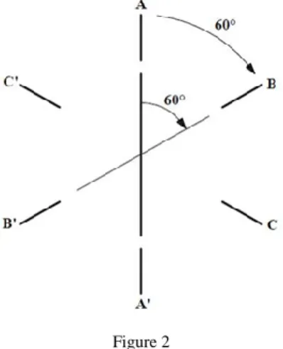
Figure 2 shows a synchronous-type VR stepping motor. The motor has three phases, six stator-teeth and two rotor-teeth. In the case of VR-steppers (or more generally, in the case stepping motors utilizing unidirectional stator magnetic fields) the minimal number of phases required to construct a symmetrical machine is three.
Figure 2
A synchronous-type variable reluctance stepping motor [7]
There are an even number of teeth belonging to each phase (on Figure 2 two teeth belong to each phase) and thus, the resultant of the forces effecting the shaft will be zero. Also, this arrangement provides a magnetically symmetrical construction.
Thus, the number of stator-teeth (𝑍1) is as follows:
𝑍1= 2𝑝𝑚∗ (7)
Where:
𝑝: the number of pole-pairs (per phases) 𝑚∗: the number of phases
2.2 Synchronous-Type Variable Reluctance Stepping Motors
In the case of synchronous-type variable reluctance stepping motors the magnetic field of the rotor is fixed to the rotor. Therefore, for the synchronous-type VR- stepper on Figure 2, from equation (5):
∆𝛼𝑠𝑡𝑎𝑡𝑜𝑟−𝑓𝑖𝑒𝑙𝑑,𝑠𝑡𝑎𝑡𝑜𝑟= 60°, ∆𝛼𝑟𝑜𝑡𝑜𝑟−𝑓𝑖𝑒𝑙𝑑,𝑟𝑜𝑡𝑜𝑟= 0°, ∆𝛼𝑟𝑜𝑡𝑜𝑟= 60°
The number of steps per revolutions (𝑆) is:
𝑆 = 𝑚∗𝑍2 (8)
Where:
𝑍2: the number of rotor-teeth
A general relationship can be derived from equation (4) if ∆𝛼𝑟𝑜𝑡𝑜𝑟 is measured in revolutions:
1 𝑍1
=
1𝑆 (9)
This means that:
𝑍1= 𝑆 (10)
Substituting equations (7) and (8) into equation (10) gives:
𝑍2= 2𝑝 (11)
This means that the number of rotor-teeth is equal with the number of poles. It must be noted that synchronous-type VR-motors are generally not used as stepping motors. Instead, they are mainly applied as high-speed switched reluctance motors [7], [8], [9], [10].
2.3 Asynchronous-Type Variable Reluctance Stepping Motors
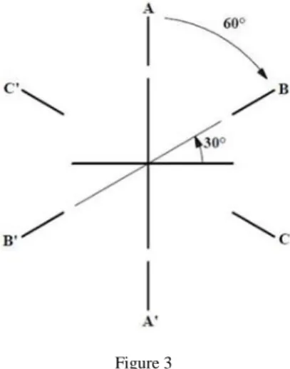
Figure 3 and Figure 4 show two asynchronous-type VR-steppers. The motor on Figure 3 has 6 teeth on the stator and 4 teeth on the rotor, therefore it can be called a 6/4 asynchronous-type VR-stepper. For similar reasons, the motor on Figure 4 can be called a 6/8 asynchronous-type VR-stepper.
Figure 3
A 6/4 asynchronous-type VR-stepper [7]
Figure 4
A 6/8 asynchronous-type VR-stepper [7]
For the 6/4 stepper, the components of equation (4) are:
∆𝛼𝑠𝑡𝑎𝑡𝑜𝑟−𝑓𝑖𝑒𝑙𝑑,𝑠𝑡𝑎𝑡𝑜𝑟= 60°, ∆𝛼𝑟𝑜𝑡𝑜𝑟−𝑓𝑖𝑒𝑙𝑑,𝑟𝑜𝑡𝑜𝑟= 90°, ∆𝛼𝑟𝑜𝑡𝑜𝑟 = −30°
Similarly, for the 6/8 stepper:
∆𝛼𝑠𝑡𝑎𝑡𝑜𝑟−𝑓𝑖𝑒𝑙𝑑,𝑠𝑡𝑎𝑡𝑜𝑟= 60°, ∆𝛼𝑟𝑜𝑡𝑜𝑟−𝑓𝑖𝑒𝑙𝑑,𝑟𝑜𝑡𝑜𝑟= 45°, ∆𝛼𝑟𝑜𝑡𝑜𝑟 = 15°
It can be concluded that the magnetic field of the rotor is moving relative to the rotor and therefore, these steppers are similar to the asynchronous (AC induction) motors.
Similarly to the case of synchronous-type VR-steppers, general relationships can be derived from equation (4):
1 𝑍1
=
1𝑍2
±
1𝑆 (12)
After a few equivalent transformations we get:
𝑆 =
|𝑍𝑍1𝑍22−𝑍1| (13)
Substituting equations (7) and (8) into equation (12) we get:
𝑍2= 𝑍1± 2𝑝 (14)
It can be concluded from (14) that there are two rotor-configurations belonging to a given stator-configuration. In general, the rotor-configuration with more teeth is chosen in order to increase the number of steps per revolutions.
Like the asynchronous (AC induction) motors, the asynchronous-type VR-steppers have “slip”, too. The “slip”-definition of an asynchronous-type VR-stepper can be derived from the slip-definition of an asynchronous (AC induction) motor.
Therefore:
"𝑠𝑙𝑖𝑝" =𝜔𝑠𝑡𝑎𝑡𝑜𝑟−𝑓𝑖𝑒𝑙𝑑,𝑠𝑡𝑎𝑡𝑜𝑟−𝜔𝑟𝑜𝑡𝑜𝑟
𝜔𝑠𝑡𝑎𝑡𝑜𝑟−𝑓𝑖𝑒𝑙𝑑,𝑠𝑡𝑎𝑡𝑜𝑟 = 𝜔𝑟𝑜𝑡𝑜𝑟−𝑓𝑖𝑒𝑙𝑑,𝑟𝑜𝑡𝑜𝑟
𝜔𝑠𝑡𝑎𝑡𝑜𝑟−𝑓𝑖𝑒𝑙𝑑,𝑠𝑡𝑎𝑡𝑜𝑟=
1 𝑍2
1 𝑍1
=𝑍1
𝑍2 (15)
The “slip” of the 6/4 stepper on Figure 3 is 1.5. This means that the rotor is rotating in the opposite direction of the stator-field and with a speed, which is half of that of the stator-field. Similarly, for the 6/8 stepper on Figure 4 the “slip” is 0.75. This means that the rotor is rotating in the same direction as the stator-field and with a speed, which is 25% of that of the stator-field.
Although the motors described above are asynchronous-type VR-steppers, these motors also have the basic characteristic of conventional synchronous-type motors, which means that the speed of these motors is independent of the load-torque and an increase in the load-torque will cause an increase in the so-called load angle.
Also, because of the unidirectional stator magnetic field, there is no need for changing the direction of the current-flow and therefore, the supply is DC, like in the case of DC-motors. Thus, it can be concluded that asynchronous-type VR- steppers have the characteristics of all basic machine types: synchronous, asynchronous (AC induction), and DC.
2.4 Increasing the Number of Steps per Revolutions
There are several solutions for increasing the number of steps per revolutions (𝑆).
One of the simplest methods is multiplying the number of teeth. This means that the magnetic field of the rotor travels a distance of several rotor-teeth instead of a distance of only one rotor-tooth, if a switching from one stator-phase to another one takes place. Let us mark the rotor-teeth multiplication coefficient with (𝑘 + 𝑙).
This coefficient is made of two components because the stator-teeth multiplication coefficient (𝑘) is not necessarily the same as the rotor-teeth multiplication coefficient. This issue can be explained by a technological reason: an increase in the number of stator-teeth will cause a decrease in the size of the stator-slots, which makes the winding-process more difficult.
Similarly to the previous cases, general relationships can be derived from equation (4) (𝑍1 marks the number of wound stator-teeth without stator-teeth multiplication):
1 𝑍1
=
𝑘+𝑙𝑍2
±
1𝑆 (16)
After a few equivalent transformations we get:
𝑆 =
𝑍1𝑍2|𝑍2−(𝑘+𝑙)𝑍1| (17)
Substituting equations (7) and (8) into equation (16) we get:
𝑍2= (𝑘 + 𝑙)𝑍1± 2𝑝 (18)
This means that there are two rotor-configurations belonging to a given stator- configuration. Figure 5 shows an example for teeth-multiplication. In practice, the teeth-multiplication coefficients can be higher.
Figure 5 Teeth-multiplication [7]
In this example 𝑚∗= 3, 𝑝 = 1, 𝑘 = 2, 𝑙 = 0, 𝑍1= 6, 𝑍2= 12 ± 2. On Figure 5 there are 10 rotor-teeth and according to (15) the “slip” is:
"𝑠𝑙𝑖𝑝" =
(𝑘+𝑙)𝑍1𝑍2
=
2∗610
= 1.2
(19)2.5 The Speed of Variable Reluctance Stepping Motors
In steady-state synchronous motors rotate on the same speed as the rotating magnetic field of stator. This speed is called the synchronous speed. It can be expressed as follows.
𝑛1=60𝑓𝑝1 (20)
Where:
𝑛1: the synchronous speed
𝑓1: the frequency of the fundamental component of the stator voltages 𝑝: the number of pole-pairs
In the case of variable reluctance stepping motors a similar expression applies:
𝑛
1=
60𝑓0𝑆
=
60𝑓1𝑍2 (21)
Where:
𝑛1: the speed of the motor in steady-state 𝑓0: the stepping frequency
𝑓1: the switching frequency for each of the stator phases, 𝑓0= 𝑚∗𝑓1 𝑍2: the number of rotor-teeth
It can be concluded from these equations that variable reluctance stepping motors are basically considered synchronous-type motors. The correspondent quantity of the number of pole-pairs is the number of rotor-teeth.
3 Permanent Magnet Stepping Motor Drives
3.1 Basic Construction
Figure 6 shows a permanent magnet (PM) stepping motor. This motor has teeth with windings on the stator and permanent magnet on the rotor.
Figure 6
A permanent magnet stepping motor [6]
Contrary to the case of variable reluctance stepping motors, the direction of the stator magnetic field is relevant, because the stator phases see constantly alternating magnetic poles before themselves. Therefore, bidirectional magnetic field is required in order to operate the motor.
It should be noted that VR-steppers are driven by only the so-called reluctance torque because the rotor is not excited and the motor is magnetically asymmetrical. The reluctance torque can be expressed as follows [8], [9], [10]:
𝑀 =1
2𝑖2 𝜕𝐿
𝜕∝ (22)
Where:
𝑖: the stator phase-current
𝐿: the self-inductance of the stator
∝: the mechanical angle of the rotor
Equation (22) assumes that only one phase is energized and the motor is operated in the linear region (the iron cores are not saturated).
In the case of PM-steppers the motor is driven by both the excitation torque and the reluctance torque. The excitation torque is (if only one phase is excited) [11]:
𝑀 = 𝑐𝜓𝑟𝑖sin𝛼𝑒 (23)
Where:
𝑐: a constant
𝜓𝑟: the amplitude of the rotor fluxvector
𝛼𝑒: the electrical angle between the stator fluxvector and the rotor fluxvector Equation (23) suggests that there is a linear relationship between the stator current of one phase and the electromagnetic torque. If only one stator phase is excited with nominal current, then for a PM-stepper the excitation torque is significantly greater than the reluctance torque. This means that 𝑀~𝑖 and therefore the application of microstepping is possible, whereas in the case of VR-steppers.
Permanent magnet stepping motors – like variable reluctance stepping motors – have two basic types: synchronous-type and asynchronous-type permanent magnet stepping motors.
3.2 Synchronous-Type Permanent Magnet Stepping Motors
Figure 6 shows a synchronous-type permanent magnet stepping motor. In order to find out the basic equations of synchronous-type permanent magnet stepping motors, the fundamental equation of stepping motor drives (equation (4)) must be utilized. For a synchronous-type stepping motor ∆𝛼𝑟𝑜𝑡𝑜𝑟−𝑓𝑖𝑒𝑙𝑑,𝑟𝑜𝑡𝑜𝑟= 0 and
∆𝛼𝑠𝑡𝑎𝑡𝑜𝑟−𝑓𝑖𝑒𝑙𝑑,𝑠𝑡𝑎𝑡𝑜𝑟= ∆𝛼𝑟𝑜𝑡𝑜𝑟. This means that for the PM-stepper on Figure 6
∆𝛼𝑠𝑡𝑎𝑡𝑜𝑟−𝑓𝑖𝑒𝑙𝑑,𝑠𝑡𝑎𝑡𝑜𝑟= ∆𝛼𝑟𝑜𝑡𝑜𝑟= 90°.
Like for synchronous-type VR-steppers, equation (9) can be derived from equation (4). For a synchronous-type permanent magnet stepping motor the following equations hold:
𝑍1= 2𝑝1𝑚∗ (24)
𝑆 = 2𝑝2𝑚∗ (25)
Where 𝑝1 and 𝑝2 are the number of stator- and rotor pole-pairs respectively. If we substitute equations (24) and (25) into equation (9), after equivalent transformations we get:
𝑝1= 𝑝2 (26)
This means that for synchronous-type PM-steppers, the number of stator pole- pairs and rotor pole-pairs is equivalent, like in the case of traditional motor drives (AC induction motors, permanent magnet synchronous motors, etc.). However, this is not true for all of the permanent magnet stepping motor drives, as we shall see for asynchronous-type PM-steppers.
3.3 Asynchronous-Type Permanent Magnet Stepping Motors
Figure 7
An asynchronous-type PM-stepper [6]
Figure 7 shows an asynchronous-type permanent magnet stepping motor. Like in the case of synchronous-type PM-steppers the fundamental equation of stepping motor drives will be utilized (equation (4)). For the PM-stepper on Figure 7 the components of equation (4) are as follows: ∆𝛼𝑠𝑡𝑎𝑡𝑜𝑟−𝑓𝑖𝑒𝑙𝑑,𝑠𝑡𝑎𝑡𝑜𝑟= 90°,
∆𝛼𝑟𝑜𝑡𝑜𝑟−𝑓𝑖𝑒𝑙𝑑,𝑟𝑜𝑡𝑜𝑟= 120°, ∆𝛼𝑟𝑜𝑡𝑜𝑟= −30°.
Like in the case of asynchronous-type VR-steppers, ∆𝛼𝑟𝑜𝑡𝑜𝑟−𝑓𝑖𝑒𝑙𝑑,𝑟𝑜𝑡𝑜𝑟≠ 0.
However, in the case of asynchronous-type VR-steppers this is true because the magnetic field of the rotor is moving relative to the rotor. The same is impossible in the case of asynchronous-type PM-steppers because the rotor-field is established by the permanent magnets fixed to the rotor. The question is then how it is possible that ∆𝛼𝑟𝑜𝑡𝑜𝑟−𝑓𝑖𝑒𝑙𝑑,𝑟𝑜𝑡𝑜𝑟≠ 0. The answer is that during a switching between stator phases the attracted pole-pairs on the rotor are changing. This means that ∆𝛼𝑟𝑜𝑡𝑜𝑟−𝑓𝑖𝑒𝑙𝑑,𝑟𝑜𝑡𝑜𝑟≠ 0 is true because the torque-forming pole-pairs on the rotor are changing.
A similar relationship to equation (12) can be derived from the fundamental equation of stepping motor drives. This is:
1 𝑍1
=
1𝑝2
±
1𝑆 (27)
Where 𝑝2 is the number of rotor pole-pairs. After a few equivalent transformations we get:
𝑆 = 𝑍1𝑝2
|𝑝2−𝑍1| (28)
This equation is similar to equation (13). It can be concluded that the number of rotor-teeth in the case of VR-steppers has the same role as the number of rotor pole-pairs in the case of PM-steppers. If we take it into consideration that equation (25) applies for asynchronous-type PM-steppers as well, then by substituting equation (25) into equation (27), the following expression can be derived:
𝑝2= 𝑍1± 𝑝1 (29)
According to equation (29) the number of rotor pole-pairs differs from the number of stator pole-pairs in the case of asynchronous-type PM-steppers. This is a significant difference from conventional electric motor drives like AC induction motor drives, permanent magnet synchronous motor drives, etc.
The “slip”-definition of asynchronous-type PM-steppers is similar to that of asynchronous-type VR-steppers. Based on equation (15), the “slip” of an asynchronous-type PM-stepper is:
"slip" =
𝑍1𝑝2 (30)
3.4 Comparison of VR-Stepper and PM-Stepper Drives
Variable reluctance stepping motors are cheaper than permanent magnet stepping motors. This is because they have a much simpler construction and they do not contain any permanent magnet. Also, VR-steppers are mechanically more robust than PM-steppers. While PM-steppers are exposed to the danger of demagnetization due to excessive currents, vibration, etc., VR-steppers do not suffer of this problem, because they do not contain any permanent magnet.
However, PM-steppers have a much higher power-density. A consequence of this is that for the same nominal power and for the same stator current PM-steppers produce more torque than VR-steppers.
In the case of VR-steppers the number of steps per revolutions (𝑆) that can be maximally achieved is much higher than in the case of PM-steppers. In fact, the main problem with PM-steppers is that they have a relatively low 𝑆. This problem can be reduced by three different ways.
The first solution is the application of microstepping. This is applicable because 𝑀~𝑖 in the case of PM-steppers. However, microstepping complicates the control of the motor [12]. The other problem with microstepping is that it does not necessarily increase the accuracy of positioning because the error in the load-angle caused by the load-torque can be significantly higher than the resolution of microstepping.
The second solution is the increasing of both the number of stator phases and the number of rotor pole-pairs. The former is very expensive, the latter is very limited.
The third solution is the application of a hybrid stepping motor.
4 Hybrid Stepping Motor Drives
4.1 Basic Construction
Hybrid stepping motors combine the advantages of VR- and PM-stepper motor drives while eliminating their problems [1]. Figure 8 shows a hybrid stepping motor.
The stator is the same as in the case of VR-steppers, including teeth- multiplication. The rotor has a special construction, however. There are two cups which are made of soft-iron material mounted on the permanent magnet rotor. The permanent magnet has a magnetic field of axial-direction and therefore the two cups have opposite magnetic polarity. Also, the two cups have teeth.
According to Figure 9 there is a tooth offset between the two cups, which means a 180° offset in electrical degrees. This is necessary because the magnetic field of the stator has the same direction at both of the cups and without the 180° offset in electrical degrees (which is in fact a one-pole offset) the resultant torque would be zero.
It is an important characteristic of the motor that – in contrast to the case of permanent magnet synchronous motors and PM-steppers – the permanent magnet on the rotor is not exposed to the danger of demagnetization due to excessive currents. This is because the stator generates a magnetic field of radial-direction while the permanent magnet on the rotor has a magnetic field of axial-direction.
Figure 8 A hybrid stepping motor [6]
Figure 9
The offset between the two cups [6]
Another important characteristic is that the number of steps per revolutions (𝑆) can be as high as in the case of VR-steppers because the achievable maximum of the number of rotor-teeth can be relatively high.
However, the torque-forming of a hybrid stepper is more similar to that of a PM- stepper: the excitation torque is dominant while the effect of the reluctance torque is less significant [13], [14]. Therefore, 𝑀~𝑖 is true for hybrid steppers, too.
There are two types of hybrid stepping motors: synchronous-type and asynchronous-type. Synchronous-type hybrid stepping motors are not used in practice because the achievable maximum of the number of steps per revolutions is lower than in the case of asynchronous-type hybrid steppers. Therefore, only asynchronous-type hybrid steppers will be discussed.
4.2 Asynchronous-Type Hybrid Stepping Motors
There are two possibilities for the excitation of the stator windings of an asynchronous-type hybrid stepper: bipolar and unipolar. Bipolar excitation is used when establishing of a bidirectional magnetic field is necessary, otherwise unipolar excitation (which establishes a unidirectional magnetic field) is sufficient.
The relationships for the number of steps per revolutions (𝑆) in the case of unipolar excitation are the same as in the case of VR-steppers including teeth- multiplication, notably equations (8), (17) and (18) are still valid. Figure 10 shows a simple hybrid stepper that is applicable for unipolar excitation. The stator winding requires only unidirectional magnetic field because the rotor-teeth always get aligned with the currently excited stator-teeth. However, in the case of hybrid steppers that are made for bipolar excitation, this is not true.
Figure 11 shows a bipolar hybrid stepper in two different positions. In the first position the required polarity of the lower stator-tooth is north because otherwise stability-problems would occur in standstill. In the second position, when the lower stator-tooth is aligned with a rotor-tooth, the required polarity of the lower stator-tooth is south, because in an aligned position the attraction between the opposite poles is required in order to hold the motor in a firm position.
Figure 10
A hybrid stepper for unipolar excitation
a. b.
Figure 11
A hybrid stepper for bipolar excitation, a) first position, b) second position
This means that in the case of bipolar hybrid steppers both the attraction between the opposite magnetic poles and the repulsion between the identical magnetic poles are utilized for torque-production. This is a significant difference from conventional electric motor drives, where the attraction of the opposite magnetic poles is utilized only.
Let us derive the basic equations of bipolar hybrid steppers. The number of steps per revolutions is:
𝑆 = 2𝑚∗𝑍2 (31)
If we compare this equation with equation (8) then we can conclude that 𝑆 has been doubled. This is because a bidirectional magnetic field can be established instead of a unidirectional one. Substituting equation (31) into the fundamental equation of stepping motor drives (equation (4)), we get:
1
𝑍1=(𝑘+𝑙)𝑍
2 ±2𝑚1∗𝑍
2
(32) Where (𝑘 + 𝑙) is the rotor-teeth multiplication coefficient. After a few equivalent transformations the following equation can be derived:
𝑍2= (𝑘 + 𝑙)𝑍1± 𝑝1 (33)
Where 𝑝1 is the number of stator pole-pairs. Substituting this back to equation (32) and after a few equivalent transformations we get:
𝑆 = 𝑍1𝑍2
|𝑍2−(𝑘+𝑙)𝑍1|=𝑍1𝑍2
𝑝1 (34)
The “slip”-definition of an asynchronous-type hybrid stepping motor is the same as in the case of a VR-stepper including teeth-multiplication, notably equation (19) is true for asynchronous-type hybrid steppers as well.
It must be mentioned that there are hybrid stepping motors that are suitable for both unipolar and bipolar control. In this case the application of bipolar excitation is more advantageous because the achievable maximum torque can be doubled.
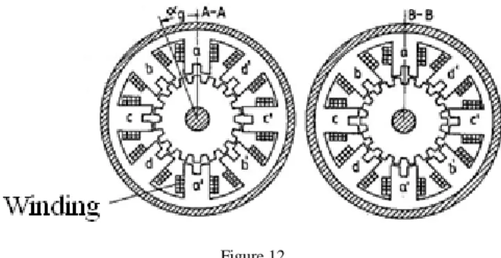
Figure 12 shows a hybrid stepper that is suitable for both unipolar and bipolar excitation.
Figure 12
A hybrid stepper for both unipolar and bipolar excitation [15]
If this motor is considered a four-phase (unipolar) stepper (phases “a”, ”b”, ”c”,
”d” are separate phases) then 𝑚∗= 4, 𝑝 = 1, 𝑘 = 2, 𝑙 = 0, 𝑍1= 8 and by substituting into equation (18) we get 𝑍2= 16 ± 2. If the motor is consider a two- phase (bipolar) stepper (phases “a” and “c” together form one phase and the same applies for phases “b” and “d”) then 𝑚∗= 2, 𝑝 = 2, 𝑘 = 2, 𝑙 = 0, 𝑍1= 8 and by substituting into equation (33) we get 𝑍2= 16 ± 2. This means that this motor is suitable for both unipolar and bipolar excitation.
5 The New Classification of Stepping Motor Drives
In the previous chapters, a new type of classification of variable reluctance, permanent magnet and hybrid stepping motor drives has been made. This new type of classification is based on the fundamental equation of stepping motor drives, the construction and the mode of excitation. Figure 13 summarizes this new type of classification.
As it can be seen on Figure 13, synchronous-type VR-steppers are used as switched reluctance motor (SRM) drives. In the case of switched reluctance motor drives teeth-multiplication is not applied, because it would make it more difficult to synchronize the stator currents to the rotor position. However, asynchronous- type VR-steppers are widely used as stepping motor drives. Teeth-multiplication can be applied in order to increase the number of steps per revolutions. In the case
of all VR-steppers, the excitation is unipolar, because only a unidirectional magnetic field is required in order to operate the motor.
Figure 13
The new classification of stepping motor drives
In the case of permanent magnet stepping motor drives, both synchronous-type and asynchronous-type steppers are used. The excitation is always bipolar, because a bidirectional magnetic field is required in order to operate the motor.
In the case of hybrid stepping motor drives only asynchronous-type steppers are used. The excitation can be unipolar or bipolar. There are certain constructions that are suitable for both unipolar and bipolar control.
Conclusions
This paper has presented the special characteristics of stepping motor drives, along with a new type of classification. In order to make this new type of classification the fundamental equation of stepping motor drives has been derived.
Based on this equation synchronous-type and asynchronous-type stepping motor drives have been distinguished. The basic equations of both types have been derived in all practical cases for all basic construction types (variable reluctance, permanent magnet and hybrid). It is an interesting conclusion of this paper that asynchronous-type steppers are far more frequently used than synchronous-type steppers.
References
[1] T. A. Khan, T. A. Taj, I. Ijaz: Hybrid Stepper Motor and its Controlling Techniques a Survey, Proceedings of the 2014 IEEE NW Russia Young Researchers in Electrical and Electronic Engineering Conference (ElConRusNW), St. Petersburg, 2014, IEEE, pp. 79-83
[2] N. Dahm, M. Huebner, J. Becker: FPGA System-on-Chip Solution for a Field Oriented Hybrid Stepper Motor Control, 9th International Multi- Conference on Systems, Signals and Devices (SSD), Chemnitz, 2012, IEEE, pp. 1-6
[3] W. Kim, C. Yang, C. C. Chung: Design and Implementation of Simple Field-Oriented Control for Permanent Magnet Stepper Motors Without DQ Transformation, IEEE Transactions on Magnetics, Vol. 47, No. 10, October 2011, pp. 4231-4234
[4] G. Müller: Theorie elektrischer Maschinen, VCH Verlagsgesellschaft mbH, D-69451 Weinheim (Bundesrepublik Deutschland), 1995, pp. 30-33 [5] Gy. Retter: Villamosenergia-átalakítók I. (In English: Electric Energy
Converters I.), Műszaki Könyvkiadó, Budapest, 1986, pp. 120-126.
[6] Microchip Technology Inc.: Microchip Webseminars: Introduction to Stepper Motors, Part 1: Types of Stepper Motors, 2007, pp. 12-25
[7] L. Szamel: The special characteristics of stepping motor drives, ENELKO, Alba Iulia, Romania, 2012, pp. 150-154
[8] J. Borka, K. Lupan, L. Szamel: Control Aspects of Switched Reluctance Motor Drives, Proceedings of the IEEE Inernational, Symposium on Industrial Electronics (ISIE'93), Budapest, 1993, pp. 1-3
[9] L. Szamel: Optimal Control of Transistor SRM Converters with Reduced Number of Switching Element, 12th International Power Electronics and Motion Control Conference (EPE-PEMC 2006), Portoroz, Slovenia, 2006, IEEE, pp. 1-4
[10] L. Szamel: Model Reference Adaptive Control of Ripple Reduced SRM Drives, Periodica Polytechnica: Electrical Engineering Vol. 46, No. 3-4, 2002, pp. 163-174
[11] S. Derammelaere, B. Vervisch, F. Verbelen, K. Stockman: Torque ripples in stepping motor driven systems, 17th European Conference on Power Electronics and Applications (EPE'15 ECCE-Europe), Geneva, 2015, IEEE, pp. 1-6
[12] B. S. Somesh, A. Mukherjee, S. Sen, P. Karmakar: Constant Current Control of Stepper Motor in Microstepping Mode using PIC16F877A, 2nd International Conference on Devices, Circuits and Systems (ICDCS), Combiatore, 2014, IEEE, pp. 1-4
[13] S. Derammelaere, C. Debruyne, F. De Belie, K. Stockman, L. Vandevelde:
Load angle estimation for two-phase hybrid stepping motors, IET Electric Power Applications, 2014, pp. 257-266
[14] S. Derammelaere, B. Vervisch, J. Cottyn, B. Vanwalleghem, P. Cox, F. De Belie, K. Stockman, L. Vandevelde, G. Van Den Abeele: The Efficiency of Hybrid Stepping Motors: Analyzing the Impact of Control Algorithms, IEEE Industry Applications Magazine, 2014, pp. 50-60
[15] I. Schmidt, Gyné Vincze, K. Veszprémi: Villamos szervo- és robothajtások (In English: Electric servo- and robot drives), Műegyetemi Kiadó, Budapest, 2000, pp. 210-212
![Figure 5 Teeth-multiplication [7]](https://thumb-eu.123doks.com/thumbv2/9dokorg/1236742.95328/9.748.267.482.200.462/figure-teeth-multiplication.webp)

![Figure 8 A hybrid stepping motor [6]](https://thumb-eu.123doks.com/thumbv2/9dokorg/1236742.95328/15.748.193.558.144.349/figure-a-hybrid-stepping-motor.webp)